
Product Overview
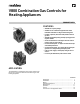
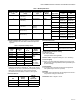

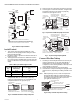
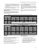
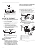
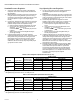
Table Of Contents

V800 COMBINATION GAS CONTROLS FOR HEATING APPLIANCES
60-2019—09 10
Standard Pressure Regulator
1. Check the manifold pressure listed on the appliance
nameplate. Gas control outlet pressure should match
the nameplate.
2. With main burner operating, check gas control flow rate
using the meter clocking method or pressure using a
manometer connected to the outlet pressure tap on the
gas control (Refer to Figures 6 or 7 depending on
model).
3. If necessary, adjust the pressure regulator to match the
appliance rating. Refer to Tables 6 or 7 for factory set
nominal outlet pressure and adjustment range.
a. Remove pressure regulator adjustment cap screw.
b. Using screw driver, turn inner adjustment screw
clockwise to increase or
counterclockwise to decrease gas pressure
to burner.
c. Always replace cap screw and tighten firmly to
prevent gas leakage.
4. If desired outlet pressure or flow rate cannot be
achieved by adjusting the gas control, check gas control
inlet pressure using a manometer at the gas control
inlet pressure tap. If inlet pressure is in the nominal
range (Refer to Tables 6 or 7), replace gas control.
Otherwise, take the necessary steps to provide proper
gas pressure on the control.
Step-Opening Pressure Regulator
1. The gas control outlet pressure should match the full
rate manifold pressure listed on the appliance
nameplate.
2. With main burner operating, check gas control flow rate
using the meter clocking method or check gas pressure
using a manometer connected to the gas control outlet
pressure tap (See Figures 6 or 7).
3. If necessary, adjust pressure regulator to match
appliance rating. Refer to Tables 6 or 7 for factory set
nominal outlet pressures and adjustment ranges.
a. Remove pressure regulator adjustment cap and
screw.
b. Using screw driver, turn inner adjustment screw
clockwise to increase or
counterclockwise to decrease gas pressure
to main burner.
c. Always replace cap screw and tighten firmly to
ensure proper operation.
4. If desired outlet pressure or gas flow rate cannot be
achieved by adjusting the gas control, check gas control
inlet pressure using a manometer at the gas control
inlet pressure tap. If inlet pressure is in the normal range
(See Tables 6 or 7), replace existing gas control.
Otherwise, take the necessary steps to provide proper
gas pressure to the control.
5. Carefully check burner lightoff at step pressure. Make
sure burner lights smoothly and without flashback to
orifice. Make sure all ports remain lit. Cycle burner
several times, allowing at least 30 seconds between
cycles for regulator to resume step function. Repeat
after allowing burner to cool. Readjust full rate outlet
pressure if necessary to improve lightoff
characteristics.
Table 6. Pressure Regulator Specification Pressures (in. wc).
a
Unregulated step pressure at 7.0 in. wc inlet pressure.
b
Unregulated step pressure at 14.0 in. wc inlet pressure.
Table 7. Pressure Regulator Specification Pressures (kPa).
a
Unregulated step pressure at 1.7 kPa inlet pressure.
b
Unregulated step pressure at 3.9 kPa inlet pressure.
Model Type of Gas
Nominal Inlet
pressure Range
Outlet Pressure
Nominal Factory Setting Setting Range
Step Full Rate Step Full Rate
VS820A,H,V;
VS821A
Natural 5.0 - 7.0 -- 3.5 -- 3.0-5.0
LP 12.0 - 14.0 -- 11.0 -- 8.0- 2.0
VS820C,
VS821C
Natural 5.0 - 7.0
0.9
a
3.5 None 3.0-5.0
LP 12.0 - 14.0
2.2
b
11.0 None 8.0-12.0
Model Type of Gas
Nominal Inlet
pressure Range
Outlet Pressure
Nominal Factory Setting
Step Full Rate Step Full Rate
VS820A, H,V;
VS821A
Natural 1.2 - 1.7 -- 0.9 -- 0.7 - 1.2
LP 2.9 - 3.9 -- 2.7 -- 2.0 - 3.0
VS820C,
VS821C
Natural 1.2 - 1.7
0.2
a
0.9 None 0.7 - 1.2
LP 2.9 - 3.9
0.5
b
2.7 None 2.0 - 2.0