
Product Overview


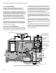

Table Of Contents

V800 COMBINATION GAS CONTROLS FOR HEATING APPLIANCES
11 60-2019—09
Check Safety Shutdown Performance
WARNING
Fire or Explosion Hazard.
Can cause property damage, severe injury or death.
Perform the safety shutdown test every time work is
done on a gas system.
1. Place gas control knob in PILOT position. Main burner
should go off and pilot should remain lit.
2. Extinguish pilot flame. Pilot gas flow should stop within
2-1/2 minutes. Safety shutoff of pilot gas proves
complete shutdown because safety shutoff valve
prohibits main burner and pilot gas flow.
3. Relight pilot burner and operate system through one
complete cycle to ensure all controls operate properly.
MAINTENANCE
WARNING
Fire or Explosion Hazard.
Can cause property damage, severe injury, or death.
Improper cleaning or reassembly may cause gas
leakage. When cleaning, ensure that control is
reassembled properly and perform gas leak test.
Regular preventive maintenance is important in applications
that place a heavy load on system controls, such as in the
commercial cooking and agricultural and industrial industries
because:
• In many such applications, particularly commercial
cooking, the equipment operates 100,000-200,000 cycles
per year. Such heavy cycling can wear out the gas control
in one to two years.
• Exposure to water, dirt, chemicals and heat can damage
the gas control and shut down the control system.
The maintenance program should include regular checkout of
the gas control as outlined under STARTUP AND CHECKOUT
and the control system as described in the appliance
manufacturer's literature.
Maintenance frequency must be determined individually for
each application. Some considerations are:
• Cycling frequency. Appliances that may cycle 100,000
times annually should be checked monthly.
• Intermittent use. Appliances that are used seasonally
should be checked before shutdown and again before the
next use.
• Consequence of unexpected shutdown. Where the cost of
an unexpected shutdown would be high, the system should
be checked more often.
• Dusty, wet or corrosive environment. Since these
environments can cause the gas control to deteriorate
more rapidly, the system should be checked more often.
The gas control should be replaced if:
• It does not perform properly on checkout or
troubleshooting.
• The gas control knob is hard to turn or push down, or it fails
to pop back up when released.
• The control is likely to have operated for more than 200,000
cycles.
OPERATION
The V800 combination gas control family provides 3-position
(OFF-PILOT-ON) manual control of gas flow. In Fig. 14, the gas
control knob is in the ON position, the pilot is proven by the
thermocouple/generator, and the thermostat is calling for
heat.
Gas Control Knob at Off
The manual safety shutoff valve and main valve are closed.
No gas flows into the control.
Gas Control Knob at Pilot
The manual safety shutoff valve and main valve are closed
until the gas control knob is manually depressed. When
depressed, the manual safety shutoff valve is opened,
allowing pilot gas flow so the pilot can be lit. After about one
minute, the thermocouple/generator current is enough, so
that power unit holds the manual shutoff valve open. The
main valve remains closed and prevents main burner gas flow
until the thermostat calls for heat.
Gas Control Knob at On; No Call for Heat
This is the standby position. The safety shutoff valve is open,
but the main valve is closed. Gas flow is restricted to the pilot
only.
Gas Control Knob at On;
Thermostat Calls for Heat
On a call for heat, the valve operator opens the left-hand port
and closes the right-hand port. Gas flows through the working
gas channel, increasing the working gas pressure. The
increased pressure pushes against the main valve diaphragm,
opening the main valve and permitting gas flow through the
control to the main burner. The servo pressure regulator
controls outlet gas pressure to the main burner.
Gas Control Knob at Off;
Thermostat Ends Call for Heat
When a call for heat ends, the valve operator closes the
left-hand port and opens the right-hand port. Gas flow
through the working gas channel is reversed, decreasing the
working gas pressure. The decreased pressure allows the
main valve diaphragm to retract and close the main valve. The
working gas flows through the evacuation channel to the gas
outlet to the main burner. The safety valve remains open,
allowing pilot gas flow.