
Install Instructions
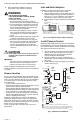
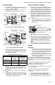
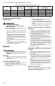


Table Of Contents

VS820 AND VS821 MILLIVOLTAGE COMBINATION GAS CONTROLS
95-6994EF—03 6
Table 6. Pressure Regulator Specification Pressures in kPa.
Check and Safety Shutdown
Performance
WARNING
FIRE OR EXPLOSION HAZARD
CAN CAUSE PROPERTY DAMAGE, SEVERE
INJURY, OR DEATH
Perform the safety shutdown test anytime work is
done on a gas system.
1. Place gas control knob in PILOT position. Main
burner should go out and pilot should remain
lit.
2. Extinguish pilot flame. Pilot gas flow should
stop within 2-1/2 minutes. Safety shutoff of
pilot gas proves complete shutdown since
safety shutoff valve blocks flow of gas to main
burner and pilot.
3. Relight pilot burner and turn gas control knob
to ON.
4. Set thermostat to call for heat and observe
appliance through one complete cycle to make
sure it operates as intended.
SERVICE
CAUTION
Never apply a jumper across (or short) valve coil
terminals. This may burn out thermostat heat
anticipator.
IMPORTANT
Allow 30 seconds after shutdown before reener-
gizing step-opening model to ensure lightoff at
step pressure.
If the Pilot Light Will Not Light
1. Make sure the main gas supply valve is open and
the pilot gas supply line is purged of air.
2. Attempt to light pilot following procedure in “Light
Pilot” on page 4.
3. Then if:
a. Pilot gas adjustment screw is closed, readjust
pilot flame. Refer to page 4.
b. Compression fitting has a gas leak, replace old
compression fitting or tighten new one. Refer to
page 3.
c. Pilot burner tubing or orifice is clogged, replace
combination gas control. Refer to page 1.
If Pilot Goes Out when Gas Control Knob is
Released
1. Make sure the gas control knob is held in at least
one minute to allow the generator time to heat.
2. Check pilot flame adjustment, refer to page 4.
3. Check the wiring between the generator and the
valve operator in the gas control.
4. Make sure jumper between valve operator and
power unit is secure and connections are clean.
Connection to power unit should be tightened 1/4
turn beyond finger tight.
5. If pilot still goes out, measure the open circuit out-
put voltages. Compare to acceptable range charts
in the generator specifications or in the Gas Con-
trols Handbook. Replace the generator if voltages
are outside the acceptable range.
6. Check power unit resistance. If above 11 ohms,
replace gas control.
If Main Burner Will Not Come On With Call
For Heat
1. Make sure gas control knob is in the ON position.
2. Adjust thermostat several degrees above room
temperature.
3. Disconnect leadwires to lower left TH terminal and
lower right PP terminal to isolate valve operator
coil from balance of circuit. Measure resistance of
coil. If coil is not 2 ohms ±10 percent, replace
Valve.
4. Measure the open generator circuit output voltages
and compare to acceptable range charts in the
generator specifications or in the Gas Controls
Handbook. Replace the generator if voltages are
outside the acceptable range.
If Burner is Overfiring
Adjust pressure regulator to correct pressure. If regulator
cannot be adjusted and supply pressure is in normal
range, replace complete gas control.
Model Type of Gas
Nominal Inlet
Pressure Range
Factory Set Nominal Outlet
Pressure Setting Range
Step Full Rate Step Range
VS820A,H,M NAT 1.2-1.7 — 0.9 — 0.7-1.2
VS821A LP 2.9-3.9 — 2.7 — 2-3
VS820C,P NAT 1.2-1.7 0.2 0.9 None 0.7-1.2
VS821C LP 2.9-3.9 0.5 2.7 None 2-3