
Install Instructions
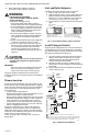
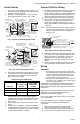
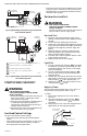
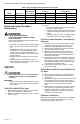
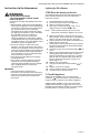


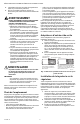
Table Of Contents

VS820 AND VS821 MILLIVOLTAGE COMBINATION GAS CONTROLS
3 95-6994EF—03
Install Control
1. This control can be mounted 0-90 degrees, in any
direction, from the upright position of the gas con-
trol knob, including vertically.
2. Mount the control so gas inlet is on the end with
projecting wrench boss. Refer to Fig. 3 and 4.
Fig. 3. Top view of standard capacity models.
Fig. 4. Top view of high capacity models.
3. Thread pipe the amount shown in Table 4 for inser-
tion into control. DO NOT THREAD PIPE TOO FAR.
Valve distortion or malfunction may result if the
pipe is inserted too deeply.
Table 4. NPT Pipe Thread Length.
4. Apply a moderate amount of good quality pipe
compound (DO NOT use Teflon tape) to pipe or
coupling only, leaving two end threads bare. On LP
installations, use compound resistant to LP gas.
Refer to Fig. 1.
5. Remove seals over control inlet and outlet, if nec-
essary.
6. Connect pipe or coupling to control inlet and outlet.
To tighten inlet and outlet connections, use wrench
on wrench boss only. Refer to Fig. 3 and 4. If tubing
is used, connect tubing to coupling.
Connect Pilot Gas Tubing
1. Cut tubing to desired length and bend as necessary
for routing to pilot burner. Do not make sharp
bends or deform tubing. Do not bend tubing at con-
trol after compression nut has been tightened, as
this may result in gas leakage at the connection.
2. Square off and remove burrs from end of tubing.
3. Unscrew brass compression fitting from the pilot
outlet (Fig. 3 or 4). Depending on gas control
model, fitting supplied may be for 1/8 or 1/4 in.
tubing. Slip the fitting over the tubing and slide out
of the way.
NOTE: When replacing a control, also replace the com-
pression fitting. Never use the old compression
fitting as it may not provide a gas-tight seal.
Refer to Fig. 5
Fig. 5. Always use new compression fitting.
4. Push tubing into the pilot gas tapping on the outlet
end of the control until it bottoms. While holding
tubing all the way in, slide fitting into place and
engage threads. Turn until finger tight. Then
tighten one more turn with wrench. Do not over-
tighten.
5. Connect other end of tubing to pilot burner accord-
ing to pilot burner manufacturer’s instructions.
Wiring
IMPORTANT
1. Since the entire control system is powered by
the millivoltage generated by the Powerpile gen-
erator, clean and scrape all wires before con-
necting. Solder and tape all necessary splices
using rosin flux to prevent corrosion.
2. Control circuit cable length must not exceed 30
ft [9 m] of 2-wire, 18 gauge cable, or 50 ft [15 m]
of 2-wire, 16 gauge cable.
Follow appliance manufacturer’s wiring instructions, if
available, or use general instructions provided below.
Where instructions differ, follow appliance manufacturer
instructions.
All wiring must comply with local electrical codes and
ordinances or with the National Electrical Code
(ANSI/NFPA 70), whichever applies.
Never connect these millivoltage controls to line voltage
or to a transformer.
To prevent electrical shock or equipment damage,
disconnect power supply before making wiring
connections.
1. After Powerpile generator is installed in pilot
burner, route generator lead to gas control.
2. Connect lead to gas control terminals labeled PP.
3. Connect thermostat leads as shown in Fig. 6 or 7.
Pipe Size
Thread Pipe This
Amount
Maximum Depth
Pipe Can Be
Inserted Into
Control
3/8 9/16 3/8
1/2 3/4 1/2
3/4 13/16 3/4
ON
OFF
PILOT
INLET
GAS
INLET
PILOTSTAT
POWER UNIT
PILOT FLOW ADJ. SCREW
(BENEATH COVER SCREW)
M17845
PILOT GAS OUTLET
PRESSURE TAPPING
DIRECTLY BENEATH
STEP-OPENING
REGULATOR (“C” MODEL)
WRENCH
BOSS
PRESSURE REGULATOR
ADJUSTMENT (BENEATH
COVER SCREW)
MANUAL GAS
CONTROL KNOB
STANDARD
PRESSURE
REGULATOR
(“A” MODEL)
INSTALL LONG
SCREW IN
OUTSIDE CORNER
TH
TR
TH
TR
M23297A
STEP-OPENING
REGULATOR
(“C” MODEL)
PRESSURE REGULATOR
ADJUSTMENT (BENEATH
COVER SCREW)
INSTALL LONG
SCREW IN
OUTSIDE CORNER
TH
TR
TH
TR
ON
OFF
PILOT
WRENCH
BOSS
MANUAL GAS
CONTROL KNOB
PILOTSTAT
POWER UNIT
PILOT FLOW ADJ. SCREW
(BENEATH COVER SCREW)
PILOT GAS OUTLET
PRESSURE TAPPING
DIRECTLY BENEATH
STANDARD
PRESSURE
REGULATOR
(“A” MODEL)
GAS
INLET
GAS CONTROL BODY
(OUTLET END)
TIGHTEN NUT ONE TURN
BEYOND FINGER TIGHT.
FITTING BREAKS OFF AND CLINCHES
TUBING AS NUT IS TIGHTENED.
TO PILOT
BURNER
M18973A