
Product Overview

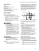


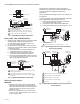

Table Of Contents

V800 COMBINATION GAS CONTROLS FOR HEATING APPLIANCES
9 60-2019—09
STARTUP AND CHECKOUT
WARNING
Fire or Explosion Hazard
Can cause property damage, severe injury or death.
1. Do not force the gas control knob. Use only your
hand to push down the reset button or turn the gas
control knob. Never use any tools.
2. If the gas control knob or reset button will not
operate by hand, or if the reset button stays
depressed after it is released, have a qualified
service technician replace the gas control.
Gas Control Knob Settings
The gas control knob has three settings:
• OFF: Prevents pilot and main burner gas flow.
• PILOT: Permits pilot gas flow only. Gas control knob must
be held depressed or thermocouple/thermopile must be
heated sufficiently to hold the Pilotstat safety control valve
open.
• ON: Permits pilot or main burner gas flow into gas control
body. Under control of thermostat and ignition module, gas
can flow to pilot and main burners.
Perform Gas Leak Test
WARNING
Fire or Explosion Hazard.
Can cause property damage, severe injury or death.
Check for gas leaks with rich soap and water solution
any time work is done on a gas control.
Gas Leak Test
1. Paint all pipe connections upstream from the gas
control with a rich soap and water solution. Bubbles
indicate a gas leak.
2. If a gas leak is detected, tighten the pipe connection.
3. Stand clear while lighting main burner to prevent injury
caused from hidden gas leaks that could cause
flashback in the appliance vestibule. Light the main
burner.
4. With the main burner in operation, paint all pipe joints
(including adapters) and gas control inlet and outlet
with rich soap and water solution.
5. If another gas leak is detected, tighten adapter screws,
joints, and pipe connections.
6. Replace the part if gas leak cannot be stopped.
Light Pilot
1. Turn gas control knob clockwise to OFF. Wait five
minutes to dissipate any unburned gas. Sniff around the
appliance near the floor. Don't relight pilot if you smell
gas.
2. Turn gas control knob counterclockwise to PILOT.
Push down and hold the knob while you light pilot
burner.
3. Hold the gas control knob down about one minute, then
release. If the pilot goes out, turn gas control knob
clockwise to OFF. Repeat steps 1-3.
4. Release gas control knob. If pilot remains lit, turn
counterclockwise to ON.
Adjust Pilot Flame
The pilot flame should envelop 3/8 to 1/ 2 in. (10 to 13 mm) of
the tip of the thermocouple or generator. See Fig. 13. To
adjust:
1. Remove pilot adjustment cover screw. Refer to Figures 6
or 7.
2. Turn inner adjustment screw clockwise to
decrease or counterclockwise to increase pilot
flame.
3. Always replace cover screw after adjustment and
tighten firmly to ensure proper operation.
Fig. 13. Proper Flame Adjustment.
Turn on Main Burner
Follow instructions provided by appliance manufacturer or
turn up thermostat to call for heat.
Check and Adjust Gas Input to Main
Burner
CAUTION
Do not exceed input rating stamped on appliance
nameplate, or manufacturer's recommended burner
orifice pressure for size orifice(s) used. Make certain
primary air supply to main burner is properly adjusted
for complete combustion. Follow appliance
manufacturer's instructions.
If checking gas input by clocking gas meter: Make
certain there is no gas flow through the meter other
than to the appliance being checked. Other appliances
must remain off with their pilots extinguished (or their
consumption must be deducted from the meter
reading). Convert flow rate to Btuh as described in
Literature No. 70-2602. Gas Controls Handbook, and
compare to the Btuh input rating on appliance
nameplate.
If checking gas input with manometer: Make certain
gas control is in PILOT position before removing outlet
pressure tap plug to connect manometer (pressure
gauge). Also turn gas control knob back to PILOT
when removing gauge and replacing plug. Before
removing inlet pressure tap plug, shut off gas supply
at the manual valve in the gas piping to the appliance
or, for LP, at the tank. Also shut off gas supply before
disconnecting manometer and replacing plug. Repeat
Gas Leak Test at plug with main burner operating.
M3086B
PROPER FLAME
ADJUSTMENT
3/8 TO 1/2 IN.
(10 TO 13 MM)
THERMOCOUPLE