
Product Overview
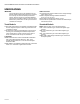
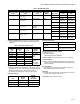

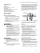


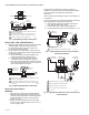

Table Of Contents

V800 COMBINATION GAS CONTROLS FOR HEATING APPLIANCES
7 60-2019—09
4. Push tubing into pilot gas tapping on outlet end of the
control until it bottoms. While holding tubing all the way
in, slide fitting into place and engage threads. Turn until
finger tight. Then tighten one more turn with wrench. Do
not overtighten.
5. Connect other end of tubing to pilot burner according to
pilot burner manufacturer's instructions.
Connect Thermocouple (24V, 100V, 120V, and
220/240V models)
The thermocouple connection to the power unit or electrical
cut-off (ECO) connector (Figures 6 and 7) is an electrical
connection and must be clean and dry. Never use pipe
compound. Tighten only 1/4 turn beyond finger tight to give
good electrical continuity.
Connect ECO (Standard capacity 24V, 100V,
120V, and 220/240V models)
If the ECO is provided, the leadwires must be equipped with
insulated 1/4 in. female quick-connect terminals. Leadwire
lengths must not exceed the lengths shown in Tables 5 and 6.
Connect the high-limit or ECO leadwires to the two terminals
on the ECO.
If ECO is not provided, connect a Q313B thermopile generator
in place of the thermocouple to act as the high-limit for the
system.
Table 4. Maximum Length of Supplementary Limit Leadwires When Using Q340A Thermocouple.
Table 5. Maximum Length of Supplementary Limit Leadwires When Using Q309A Thermocouple.
WIRING
Follow wiring instructions furnished by appliance
manufacturer, if available, or use general instructions provided
below. Where instructions differ, follow appliance
manufacturer's instructions.
All wiring must comply with applicable electrical codes and
ordinances or with the National Electrical Code
(ANSI/NFPA 70), whichever applies.
Disconnect power supply before making wiring connections
to prevent electrical shock or equipment damage.
Wiring 24V Models
NOTE: The V800 and V801 have a blue terminal block.
Terminals and markings are identical.
1. Make sure the power supply rating on each control
matches the available supply. Install transformer, low
voltage thermostat, and other controls as required.
2. Connect control circuit to operator terminals. Refer to
Fig. 9 for typical 24V wiring diagram.
3. Adjust thermostat heat anticipator to 0.2 A rating
stamped on valve operator.
Thermocouple Length
Maximum Leadwire Length x 2 (Wires)
AWG No. 14 AWG No. 16 AWG No. 18
Inches Meters Inches Meters Inches Meters Inches Meters
18 0.5 35 0.9 22 0.6 13 0.3
24 0.6 29 0.7 18 0.5 11 0.3
30 0.8 23 0.6 15 0.4 9 0.2
36 0.9 17 0.4 11 0.3 6 0.2
48 1.2
DO NOT USE
72 1.8
Thermocouple Length
Maximum Leadwire Length x 2 (Wires)
AWG No. 14 AWG No. 16 AWG No. 18
Inches Meters Inches Meters Inches Meters Inches Meters
12 0.3 47 1.2 30 0.8 18 0.5
18 0.5 41 1.0 26 0.7 16 0.4
24 0.6 35 0.9 22 0.6 14 0.4
30 0.8 29 0.8 18 0.5 11 0.3
36 0.9 23 0.6 15 0.4 9 0.2
40 1.0 19 0.5 12 0.3 7 0.2
48 1.2 11 0.3 7 0.2
60 1.5 DO NOT USE