
Install Instructions

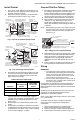
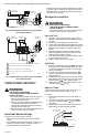

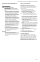

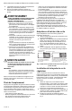
Table Of Contents

VS820 AND VS821 MILLIVOLTAGE COMBINATION GAS CONTROLS
95-6994EF—03 4
Fig. 6. Typical wiring connections for gas control with
three-terminal operator.
Fig. 7. Typical wiring connections for gas control with
four-terminal operator.
STARTUP AND CHECKOUT
WARNING
FIRE OR EXPLOSION HAZARD
CAN CAUSE PROPERTY DAMAGE, SEVERE
INJURY, OR DEATH
1. Do not force the gas control knob. Only use you
hand to push down or turn the gas control
knob. Never use any tools.
2. If the gas control knob will not operate by hand,
or if the knob stays depressed after it is
released, the control should be replaced by a
qualified service technician.
3. Perform the gas leak test described below any
time work is done on a gas system.
Gas Knob Control Settings
The gas control knob has three settings:
• OFF prevents pilot and main gas flow through the
control.
• PILOT permits gas flow to pilot burner as long as gas
control knob is held down or generator current is
above the power unit dropout value.
• ON permits gas flow into the combination gas control
body. Pilot gas is controlled as in the PILOT position.
Main burner gas is controlled by the thermostat and
automatic valve operator.
Perform Gas Leak Test
WARNING
FIRE OR EXPLOSION HAZARD
CAN CAUSE PROPERTY DAMAGE, SEVERE
INJURY, OR DEATH
Check for gas leaks with soap and water solution
any time work is done on a gas system.
Gas Leak Test:
1. Pain pipe connections upstream of gas control
with rich soap and water solution. Bubbles indicate
gas leak.
2. If leak is detected, tighten pipe connections.
3. Stand clear of main burner while lighting to prevent
injury caused from hidden leaks which could cause
flashback in the appliance vestibule. Light main
burner.
4. With main burner in operation, paint pipe joints
(including adapters) and control inlet and outlet
with rich soap and water solution.
5. If another leak is detected, tighten adapter screws,
joints, and pipe connections.
6. Replace part if leak can’t be stopped.
Light Pilot
1. Turn gas control knob clockwise to OFF. Wait
five minutes to dissipate any unburned gas. Sniff
around the appliance near the floor. Don’t relight
pilot if you smell gas.
2. Turn gas control knob counterclockwise to
PILOT. Push down and hold the knob while you
light pilot burner.
3. Hold the gas control knob down about one minute,
then release. If the pilot goes out, turn gas control
knob clockwise to OFF. Repeat steps 1-3.
4. Release gas control knob. If pilot remains lit, turn
counterclockwise to ON.
Adjust to Flame
The pilot flame should envelop 3/8 to 1/2 in. [10 to 13
mm] of the tip of the generator. Refer to Fig. 8.
To adjust:
1. Remove pilot adjustment cover screw. Refer to
Fig. 2 or 3.
2. Turn inner adjustment screw clockwise to
decrease or counterclockwise to increase
pilot flame.
3. Always replace cover screw after adjustment and
tighten firmly to ensure proper operation.
Fig. 8. Proper flame adjustment.
M36107
HIGH LIMIT
CONTROLLER
POWERPILE
THERMOSTAT
TH
PP
TH
PP
POWER UNIT CONTROL
OPERATOR COIL
M36108
HIGH LIMIT
CONTROL
POWERPILE
THERMOSTAT
TH
PP
2
1
1
COMBINATION SCREW, 1/4 INCH QUICK-CONNECT TERMINALS (4).
POWER PILE OPERATOR COIL (INTERNAL WIRING).
MUST BE APPROVED SAFETY-CIRCUIT WIRING.
PILOTSTAT POWER UNIT COIL (INTERNAL WIRING.)
ECO, IF USED.
2
3
4
5
5
4
TH
PP
3
POWERPILE
GENERATOR
M18972A
PROPER FLAME
ADJUSTMENT
3/8 TO 1/2 IN.
(10 TO 13 MM)
GENERATOR