
Product Overview
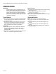
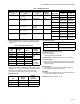
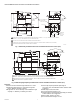
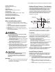
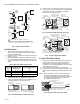
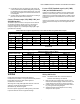
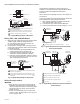
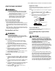
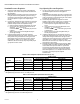
Table Of Contents

V800 COMBINATION GAS CONTROLS FOR HEATING APPLIANCES
60-2019—09 8
Fig. 9. Typical Wiring Hookup for 24V Systems.
Wiring 110V, 120V, 220/240V Models
1. Make sure power supply rating on each control matches
available supply. Install line voltage thermostat
(or controller) and other controls as required. See
Fig. 10 for typical wiring diagram.
2. Use junction box, as shown, when connecting control
circuit to gas control operator. Make conduit connection
to operator as follows:
a. Slip conduit fittings over integral leadwires and
screw securely into hole in operator cover.
b. Cut flexible conduit to appropriate length. Slip
conduit over leadwires and attach to fittings.
c. Route and connect both flexible conduits to junction
box. Connect integral wires to control circuit. Do not
splice except within a junction box.
Fig. 10. Typical Wiring Hookup for 120V System.
Wiring Powerpile Models
IMPORTANT
1. Since the entire control system is powered by the
millivoltage generated by the Powerpile generator,
clean and scrape all wires before connecting. Solder
and tape all necessary splices using rosin flux to
prevent corrosion.
2. Control circuit cable length must not exceed 30 ft.
(9 mm) of 2-wire, 18 gauge cable, or 50 ft. (15 m) of
2-wire, 16 gauge cable.
Follow appliance manufacturer's wiring instructions, if
available, or use general instructions provided below. Where
instructions differ, follow appliance manufacturer
instructions.
Never connect these millivoltage controls to line voltage or to
a transformer.
To prevent electrical shock or equipment damage, disconnect
power supply before making wiring connections.
1. After Powerpile generator is installed in pilot burner,
route generator lead to gas control.
2. Connect lead to gas control terminals labeled PP.
3. Connect thermostat leads as shown in Figures 11 or 12.
Fig. 11. Typical Wiring Connections for Gas Control with
Three-Terminal Operator.
Fig. 12. Typical Wiring Connections for Gas Control with Four-
Terminal Operator
ECO LIMIT
THERMOCOUPLE
ECO
CONNECTOR
POWER
UNIT
POWER SUPPLY. PROVIDE DISCONNECT MEANS AND OVERLOAD
PROTECTION AS REQUIRED.
NEVER JUMPER THESE TERMINALS. THIS SHORTS OUT VALVE
COIL AND MAY BURN OUT HEAT ANTICIPATOR IN THERMOSTAT.
ORDER ECO LIMIT AND LEADWIRES SEPERATELY.
1
2
3
24 VOLT
THERMOSTAT
TH
TR
TH
TR
M23299
3
2
1
L1
(HOT)
L2
TRANSFORMER
CAUTION
SEE
HIGH LIMIT
CONTROLLER
POWER SUPPLY. PROVIDE DISCONNECT MEANS AND OVERLOAD
PROTECTION AS REQUIRED.
LINE VOLTAGE ENCLOSURE NOT PART OF GAS CONTROL. LINE
VOLTAGE GAS CONTROLS MUST BE USED IN AN OEM APPROVED
ENCLOSURE.
1
2
M23300
1
L1
(HOT)
L2
LIMIT
CONTROLLER
2
LINE VOLTAGE
OPERATOR
LINE VOLTAGE
THERMOSTAT OR
CONTROLLER
JUNCTION BOX
M23301
HIGH LIMIT
CONTROLLER
POWERPILE
THERMOSTAT
TH
TR
TH
PP
1
1
1
POWERPILE OPERATOR COIL (INTERNAL WIRING).
POWER UNIT CONTROL
M27093
HIGH LIMIT
CONTROL
POWERPILE
THERMOSTAT
TH
PP
2
1
1
COMBINATION SCREW, 1/4 INCH (6) QUICK-CONNECT TERMINALS (4).
POWER PILE OPERATOR COIL (INTERNAL WIRING).
MUST BE APPROVED SATETY-CIRCUIT WIRING.
PILOTSTAT POWER UNIT COIL (INTERNAL WIRING.)
ECO, IF USED.
2
3
4
5
5
4
TH PP
3
POWERPILE
GENERATOR