
Product Overview
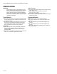
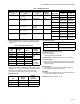
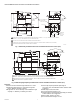
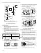
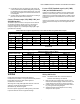
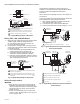
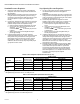
Table Of Contents

V800 COMBINATION GAS CONTROLS FOR HEATING APPLIANCES
5 60-2019—09
Optional Specifications:
Inlet pressure tap, 1/8 in. NPT.
Side outlets.
Replacement Parts:
392451-1 Energy Cutoff (ECO) connector.
Valve Operators
Powerpile Operator: VS824.
Modusnap Operator with modulating control: V5306.
Servo Gas Pressure Regulators.
Standard Pressure Regulator: V5306.
Step-opening pressure regulator: V5307.
INSTALLATION
When installing this product:
1. Read these instructions carefully. Failure to follow
instructions can damage product or cause a hazardous
condition.
2. Check ratings given in instructions and on product to
make sure product is suitable for your application.
3. Make sure installer is a trained, experienced service
technician.
4. After completing installation, use these instructions to
check out product operation.
WARNING
Fire or Explosion Hazard
Can cause property damage, severe injury or death.
Follow this warning exactly.
1. To avoid dangerous accumulation of fuel gas, turn
off gas supply at appliance service valve before
starting installation and perform Gas Leak Test after
completion of installation.
2. Do not bend pilot tubing at the control or pilot after
compression nut has been tightened. Gas leakage
at the connection may result.
3. Always install sediment trap in gas supply line to
prevent contamination of gas control.
4. Do not force gas control knob. Use only your hand to
turn gas control knob. Never use any tools. If gas
control knob will not operate by hand, the control
should be replaced by a qualified service technician.
Force or attempted repair may result in fire or
explosion.
CAUTION
Disconnect power supply before wiring to prevent
electrical shock or equipment damage.
Never apply a jumper across (or short) valve coil
terminals. This may burn out heat anticipator in
thermostat.
IMPORTANT
These gas controls are shipped with protective seals
over inlet and outlet tappings. Do not remove seals
until ready to connect piping.
Optional Piping Patterns—Trade Models
To facilitate installation, trade models incorporate side outlets
in the standard straight-through body. See Fig. 3. To fit
existing piping, reducer fittings also are included. These
controls are shipped with side outlets plugged as shown. If
connection is made to optional side outlet, be sure to install
plug in standard straight-through outlet tapping. Use plug
removed from side outlet. Perform Gas Leak Test when
installation is complete.
Fig. 3. Optional Side Outlets (Standard Capacity Models only).
Follow appliance manufacturer's instructions if available;
otherwise, use instructions provided below as a guide.
Location
Do not locate the combination gas control where adverse
environments such as steam cleaning, high humidity or
dripping water, corrosive chemicals, dust or grease
accumulation, or excessive heat are prevalent. To ensure
proper operation, follow these guidelines:
• Locate in a well ventilated area.
• Mount high enough above the cabinet bottom to avoid
exposure to flooding or splashing water.
• Ensure that the ambient temperature does not exceed the
ambient temperature ratings for each component.
• Cover if appliance is cleaned with water, steam, or
chemicals or to avoid dust and grease accumulation.
• Avoid locating where exposure to corrosive chemical
fumes or dripping water is likely.
Mount the combination gas control in the appliance vestibule
on the gas manifold. If this is a replacement application,
mount the control in same location as old control.
Install Piping to Control
All piping must comply with local codes and ordinances or
with National Fuel Gas Code (ANSI Z223.1 NFPA No. 54),
whichever applies. Tubing installation must comply with
approved standards and practices.
1. Use new, properly reamed pipe free from chips. If tubing
is used, make sure ends are square, deburred, and clean.
All tubing bends must be smooth and without deforma-
tion.
2. Run pipe or tubing to the control. If tubing is used,
obtain a tube-to-pipe coupling to connect tubing to the
control.
3. Install sediment trap in gas supply line (Refer to Fig. 4).
MANUAL GAS
CONTROL KNOB
M23295
INLET
WRENCH
BOSS
LEFT SIDE
OUTLET
RIGHT
SIDE
OUTLET
STANDARD
OUTLET
STRAIGHT
THROUGH
1-9/16 (40)
1-9/16 (40)
2-9/16 (65)
4-1/16 (103)