
Product Overview
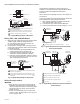


Table Of Contents

V800 COMBINATION GAS CONTROLS FOR HEATING APPLIANCES
13 60-2019—09
SERVICE
WARNING
Fire or explosion hazard.
Can cause property damage, severe injury or death.
Do not disassemble the gas control; it contains no
replaceable components. Attempted disassembly or
repair will damage the gas control.
CAUTION
Equipment Damage Hazard.
Can cause property damage.
Do not apply a jumper across or short the valve coil
terminals. This may burn out the heat anticipator in
the thermostat.
IMPORTANT
Allow 60 seconds after shutdown before re-
energizing the step-opening model to ensure lightoff
at step pressure.
If the Pilot will not light
1. Ensure the main gas supply valve is open and the pilot
gas supply line is purged of air.
2. Attempt to light pilot burner flame following procedures
in Light Pilot section. If pilot still will not light:
a. Check the pilot gas adjustment screw. If closed,
readjust the pilot flame. Refer to Adjust the Pilot
Burner Flame section.
b. Perform the Gas Leak Test at the compression
fitting. If a gas leak is detected, replace the old
compression fitting or tighten the newly installed
one (Refer to Fig. 8).
c. Ensure that the pilot burner tubing or pilot burner
orifice is not clogged. If clogged, replace
combination gas control.
If the Pilot goes out when the gas control knob
is released
1. Ensure the gas control knob is held in at least one
minute to allow the thermocouple or generator time to
heat.
2. Adjust thermostat several degrees above room
temperature.
3. For VS820 and VS821, disconnect leadwires to lower
left TH terminal and lower right PP terminal to isolate
valve operator coil from balance of circuit. Measure
resistance of coil. If coil is not 2 ohms ± 10 percent,
replace VS824A Valve Operator.
4. In Powerpile applications, ensure jumper between valve
operator and power unit is secure and connections are
clean.
5. In thermocouple applications, ensure connection to
power unit is tightened 1/4 turn beyond finger tight.
6. If pilot still goes out, measure the open and closed
thermocouple or generator circuit output voltages.
Compare it to the acceptable range charts in the
thermocouple or generator specifications or in the Gas
Controls Handbook. Replace the thermocouple or
generator circuit if voltages are outside the acceptable
range.
7. Check the power unit resistance. If above 11 ohms,
replace the gas control.
If the Main Burner will not come on with a call
for heat
1. Ensure the gas control knob is in the ON position.
2. Adjust the thermostat several degrees above room
temperature.
3. For VS820 and VS821, disconnect leadwires to lower
left the TH terminal and lower right PP terminal to
isolate valve operator coil from balance of circuit.
Measure resistance of coil. If coil is not 2 ohms ± 10
percent, replace VS824A Valve Operator.
4. For all other models, use an ac voltmeter to measure the
voltage across terminals TH and TR.
a. If no voltage is present, check the control circuit for
proper operation.
b. If proper control system voltage is present, but first
operator did not “click“ open, check for excessive
inlet gas pressure. If inlet gas pressure is correct,
replace the gas control.
c. If proper control system voltage is present and first
valve operator “clicked” open, replace second
operator assembly.
5. Measure the open and closed thermocouple or
generator output voltages and compare to the
acceptable range charts in the thermocouple or
generator specifications or in the Gas Controls
Handbook. Replace the thermocouple or generator if
voltages are outside the acceptable range.
If Burner is overfiring
Adjust the gas control pressure regulator to the correct
pressure. If the regulator cannot be adjusted and supply
pressure is in the normal range, replace the gas control.