
Install Instructions

VR8245 AND VR8345 ELECTRONIC IGNITION GAS CONTROLS
9 69-2013—04
Check And Adjust Gas Input to Main
Burner
CAUTION
Fire or explosion hazard.
1. Do not exceed the input rating stamped on the
appliance nameplate, or manufacturer
recommended burner orifice pressure for the
size orifice(s) used. Make certain the primary
air supply to the main burner is properly
adjusted for complete combustion (refer to the
appliance manufacturer instructions).
2. WHEN CHECKING GAS INPUT BY CLOCKING
THE GAS METER:
• Make sure that the only gas flow through the
meter is that of the appliance being checked.
• Make certain that other appliances are
turned off with pilot burners extinguished (or
deduct that gas consumption from the meter
reading).
• Convert the flow rate to Btuh as described in
Gas Controls Handbook, form 70-2602, and
compare to the Btuh input rating on the
appliance nameplate.
3. WHEN CHECKING GAS INPUT WITH A
MANOMETER (PRESSURE GAUGE):
• To connect the manometer, be sure the gas
control knob is in the OFF position before
removing the outlet pressure tap plug.
• When removing the manometer, turn the gas
control knob back to OFF and replace the
outlet pressure tap plug.
• Shut off the gas supply at the appliance
service valve, or at the gas tank for LP gas,
before removing the outlet pressure tap plug
and before disconnecting the manometer
and replacing the outlet pressure tap plug.
• Perform the Gas Leak Test at the outlet
pressure tap plug.
Standard-Opening Pressure Regulator
1. The gas control outlet pressure should match the
manifold pressure listed on the appliance name-
plate.
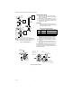
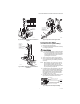
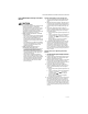
2. With the main burner operating, check the gas con-
trol flow rate by using the meter clocking method
or check the gas pressure using a manometer con-
nected to the gas control outlet pressure tap. See
Fig. 3.
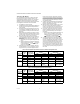
3. If necessary, adjust the pressure regulator to
match the appliance rating. Refer to Table 6 for the
factory set nominal outlet pressures and adjust-
ment setting ranges.
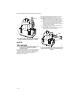
a. Remove the pressure regulator adjustment cap
screw.
b. Using a screwdriver, turn the inner adjustment
screw clockwise to increase or counter-
clockwise to decrease the main burner gas
pressure.
c. Always replace the cap screw and tighten
firmly to safeguard proper operation.
4. If the desired outlet gas pressure or gas flow rate
cannot be achieved by adjusting the gas control,
check the gas control inlet pressure by using a
manometer at the inlet pressure tap. If the inlet
pressure is in the normal range (refer to Table 6
and 7), replace the gas control. Otherwise, take the
necessary steps to provide proper gas pressure to
the gas control.
Standard and Slow-Opening (H and M)
Models
1. Carefully check the main burner lightoff. Make sure
that the main burner lights smoothly and that all
ports remain lit.
2. Check the full rate manifold pressure listed on the
appliance nameplate. Gas control full rate outlet
pressure should match this rating.
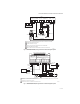
3. With main burner operating, check the control flow
rate using the meter clocking method or check
pressure using a manometer connected to the out-
let pressure tap on the control. See Fig. 3.
4. If necessary, adjust the pressure regulator to
match the appliance rating. See Table 6 and 7 for
factory-set nominal outlet pressure and adjust-
ment range.
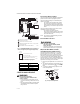
a. Remove the pressure regulator adjustment cap
screw.
b. Using a screwdriver, turn the inner adjustment
screw (Fig. 3) clockwise to increase or
counterclockwise to decrease the gas
pressure to the burner.
c. Always replace the cap screw and tighten
firmly to prevent gas leakage.
5. If the desired outlet pressure or flow rate cannot be
achieved by adjusting the gas control, check the
gas control inlet pressure using a manometer at
the inlet pressure tap of the gas control. If the inlet
pressure is in the nominal range (see Table 6 and
7), replace the gas control. Otherwise, take the nec-
essary steps to provide proper gas pressure to the
control.