
Install Instructions


VR8245 AND VR8345 ELECTRONIC IGNITION GAS CONTROLS
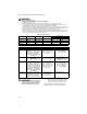
69-2013—04 8
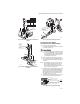
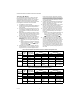
Fig. 12. VR8245M/VR8345M,H wiring connections in
direct spark ignition system (single rod application).
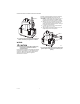
Fig. 13. VR8345Q wiring diagram.
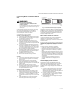
STARTUP AND CHECKOUT
WARNING
FIRE OR EXPLOSION HAZARD
CAN CAUSE PROPERTY DAMAGE, SEVERE
INJURY, OR DEATH
1. Do not force the gas control knob. Use only
your hand to turn the gas knob. Never use any
tools.
2. If the gas control knob will not operate by hand,
call a qualified service technician to replace
the gas control.
Gas Control Knob Settings
The gas control knob operates differently in intermittent
pilot, hot surface and direct spark ignition systems.
The gas control knob settings for an intermittent pilot
system are as follows:
OFF: Prevents pilot and main burner gas flow.
ON: Permits gas to flow into the control body.
Under control of the thermostat and intermittent
pilot module, gas can flow to the pilot and main
burner.
The gas control knob settings for hot surface or direct
spark ignition systems are as follows:
OFF: Prevents main burner gas flow.
ON: Permits main burner gas flow. Under control
of the thermostat and ignition module, gas can
flow to the main burner.
NOTE: Gas controls are shipped with the gas control
knob in the ON position.
Perform Gas Leak Test
WARNING
FIRE OR EXPLOSION HAZARD
CAN CAUSE PROPERTY DAMAGE, SEVERE
INJURY, OR DEATH
Check for gas leaks with a rich soap and water
solution anytime work is done on a gas control.
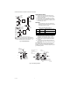
Adjust the Pilot Burner Flame
(Intermittent Pilot Ignition only)
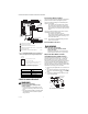
The pilot flame should envelop 3/8 to 1/2 in. [10 to 13
mm] of the igniter-sensor tip. See Fig. 14. If the pilot
flame is small or lazy, or does not touch the ground
electrode or thermocouple, the inlet gas pressure may be
too low, or the pilot orifice may be partially clogged.
Check and repair as necessary. If the pilot flame is hard
and noisy, the inlet gas pressure may be too high. If pilot
adjustment is necessary, proceed as follows:
1. Remove the pilot adjustment cover screw. Refer to
Fig. 3.
2. Turn the inner adjustment screw clockwise to
decrease or counterclockwise to increase pilot
flame.
3. To prevent gas leakage, always replace the cover
screw after adjustment.
Fig. 14. Proper flame adjustment.
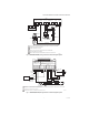
Valve terminals: Typically connects to:
Hi W2, Hi
Mv or Lo Mv, Lo, Valve
CMv/Pv, Valve
Pv Pv
24V
24V (GND)
S87 CONTROL MODULE
ALARM
VALVE
VALVE
GND
TEMPERATURE
CONTROLLER
POWER SUPPLY. PROVIDE DISCONNECT MEANS AND OVERLOAD
PROTECTION AS REQUIRED.
ALTERNATE LIMIT CONTROLLER LOCATION.
MAXIMUM IGNITER-SENSOR CABLE LENGTH: 3 FT [.9 M] OR LESS.
3A REPLACEABLE FUSE.
ALARM TERMINAL PROVIDED ON SOME MODELS.
M23472
MV
MV
L1
(HOT)
L2
1
2
1
2
3
VALVE
Q347 IGNITER-SENSOR
BURNER
4
4
5
IGNITER-SENSOR AND
BURNER GROUND
3
5
ALARM,
IF USED
QUICK
CONNECTS
DSI WIRE
ADAPTER
2-STAGE
GAS VALVE
HI
MV
PV
C
SECOND STAGE OR HIGH FIRE
MAIN VALVE OR LO FIRE
PILOT VALVE FOR INTERMITTENT IGNITION ONLY
COMMON TERMINAL OF IGNITION COILS
M23473
PROPER FLAME
ADJUSTMENT
IGNITER-
SENSOR
M3080A
3/8 TO 1/2 INCH
(10 TO 13 mm)