
Install Instructions


VR8245 AND VR8345 ELECTRONIC IGNITION GAS CONTROLS
69-2013—04 6
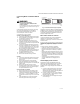
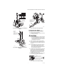
Fig. 8. Remove pilot gas seal (plug) and install pilot gas
tube for intermittent pilot application on VR8345.
WIRING
CAUTION
Disconnect power supply before making wiring
connections to prevent electrical shock or
equipment damage.
Follow the wiring instructions furnished by the appliance
manufacturer, if available, or use the following general
instructions. Where these instructions differ from the
appliance manufacturer, follow the appliance
manufacturer instructions.
All wiring, including insulated quick connect terminals,
must comply with applicable electrical codes and
ordinances.
1. Check the power supply rating on the gas control
and make sure it matches the available supply.
Install thermostat and other controls as required.
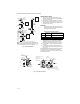
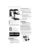
2. When the gas control is installed on a hot surface
or direct spark ignition system, attach the wire
adapter provided to the wiring terminals. See Fig. 9
for the wire terminal location.
3. Connect control circuit to gas control terminals.
See Fig. 3 and 10, 11, 12, or 13.
4. Adjust the thermostat heat anticipator to 0.7, the
rating stamped on the valve operator.
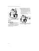
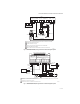
Fig. 9. Install wire adapter for hot surface or direct spark
ignition systems. Pilot plug must be in the valve pilot
opening.
M8441A
PV
MV
PV
MV
OFF
ON
PILOT GAS
TUBE
M8440A
PV
MV
PV
MV
OFF
ON
PILOT GAS SEAL
(PLUG)
WIRE
ADAPTER