
Install Instructions

VR8245 AND VR8345 ELECTRONIC IGNITION GAS CONTROLS
69-2013—04 10
Two-Stage (Q) Models
Two-stage models require that you check and adjust
both high and low pressure regulator settings. Two-
stage appliance operating sequences vary. Consult the
appliance manufacturer instructions for the specific
operating sequence and regulator adjustment procedure
for the appliance in which the control is installed.
1. Set appliance to operate on high.
2. Carefully check the main burner lightoff. Make sure
that the main burner lights smoothly and that all
ports remain lit.
3. Check the full rate (high) manifold pressure listed
on the appliance nameplate for high pressure. The
gas control full rate outlet pressure should match
this rating.
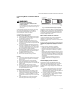
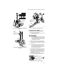
4. With main burner operating, check the gas control
flow rate using the meter clocking method or check
pressure using a manometer connected to the out-
let pressure tap on the gas control. See Fig. 3.
5. If necessary, adjust the high pressure regulator to
match the appliance rating. See Table 6 and 7 for
factory-set nominal outlet pressure and adjust-
ment range.
a. Remove the pressure regulator adjustment cap
(Fig. 3).
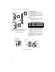
b. Using a screwdriver, turn the inner adjustment
screw for HI pressure clockwise to increase
or counterclockwise to decrease the gas
pressure to the burner.
6. After high pressure has been checked, check low
pressure regulation. Two-stage appliance operat-
ing sequences vary. Consult the appliance manu-
facturers instructions for the specific operating
sequence and regulator adjustment procedure for
the appliance in which the control is installed and
for instructions on how to prevent the control from
moving to high stage while checking the low pres-
sure regulator setting.
7. Check the low rate manifold pressure listed on the
appliance nameplate. Gas control low rate outlet
pressure should match this rating.
8. With main burner operating, check the gas control
flow rate as before (using the meter clocking
method or check pressure using a manometer con-
nected to the outlet pressure tap on the control).
9. If necessary, adjust the low pressure regulator to
match the appliance rating. See Table 6 and 7 for
factory-set nominal outlet pressure and adjust-
ment range.
a. Remove the pressure regulator adjustment cap
(Fig. 3). Using a screwdriver, turn the inner
adjustment screw for LO pressure clockwise
to increase or counterclockwise to
decrease the gas pressure to the burner.
10. Once high and low pressure have been checked
and adjusted, replace pressure regulator adjust-
ment cap. If the desired outlet pressure or flow rate
cannot be achieved by adjusting the gas control,
check the control inlet pressure using a manome-
ter at the inlet pressure tap of the control. If the
inlet pressure is in the nominal range (see Table 6
and 7), replace the gas control. Otherwise, take the
necessary steps to provide proper gas pressure to
the control.
a
Low Fire setting range for VR8304Q 1/2 in. by 1/2 in. and 1/2 in. by 3.4 in. is 1.5 to 3.0 in. wc.
a
Low Fire setting range for VR8304Q 1/2 in. by 1/2 in. and 1/2 in. by 3.4 in. is 0.37 to 0.75 kPa.
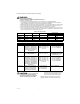
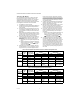
Table 6. Pressure Regulator Specification Pressures for Standard-Opening Natural Gas.
Model Type
Type of
Gas
Nominal Inlet
Pressure Range
Factory Set Nominal Outlet
Pressure Setting Range
Step Full Rate Step Full Rate
Standard,
Slow
NAT 5.0 to 7.0 — 3.5 — 3.0 to 5.0
LP 12.0 to 14.0 — 10.0 — 8.0 to 12.0
Step NAT 5.0 to 7.0 0.9 3.5 None 0.7 to 1.7
LP 12.0 to 14.0 2.2 10.0 None 1.4 to 5.5
Two-Stage NAT 5.0 to 7.0 — 1.7 Low
3.5 High
—
0.9 to 3.0 Low
a
3.0 to 5.0 High
LP 121.0 to 14.0 — 4.9 Low
10.0 High
— 2.5 to 7.0 Low
8.0 to 11.0 High
Table 7. Pressure Regulator Specification Pressures (kPa).
Model Type
Type of
Gas
Nominal Inlet
Pressure Range
Factory Set Nominal Outlet
Pressure Setting Range
Step Full Rate Step Full Rate
Standard,
Slow
NAT 1.2 to 1.7 — 0.9 — 0.7 to 1.2
LP 2.9 to 3.9 — 2.5 — 2.0 to 3.0
Step NAT 1.2 to 1.7 0.2 0.9 None 0.7 to 1.7
LP 2.9 to 3.9 0.5 2.5 None 1.4 to 5.5
Two-Stage NAT 1.2 to 1.7 — 0.48 Low
0.9 High
—
0.22 to 0.75 Low
a
0.75 to 1.2 High
LP 2.9 to 3.9 — 1.2 Low
2.5 High
— 0.6 to 1.8 Low
2.0 to 2.5 High