
NG to LP Conversion Guide
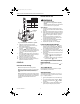
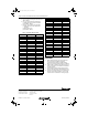
Table Of Contents
- Application
- Installation
- Start-up
- Gas Control Knob Settings
- Perform Gas Leak Test
- Light Pilot (Standing Pilot Models)
- Turn on System (Intermittent and Direct Ignition Systems)
- Turn on Main Burner
- Adjust Pilot Flame
- Check and Adjust Gas Input and Burner Ignition
- Checking Gas Pressure Using Meter Clocking Method
- Checking Gas Pressure Using a Manometer (Pressure Gauge)
- Checkout

393691 LP GAS AND 394588 NATURAL GAS CONVERSION KITS
3 69-0244—7
Fig. 3. Proper flame adjustment.
Check and Adjust Gas Input and Burner
Ignition
CAUTION
Equipment Damage Hazard.
Exceeding input ratings can damage the
equipment.
1. Do not exceed input rating stamped on
appliance nameplate, or manufacturer
recommended burner orifice pressure for size
orifice(s) used. Make certain primary air supply
to main burner is properly adjusted for
complete combustion. Follow appliance
manufacturer instructions.
2. IF CHECKING GAS INPUT BY CLOCKING
GAS METER:
a. Make sure that the only gas flowing
through the meter is for the appliance being
checked.
b. Make certain that other appliances are
turned off with their pilot flames extinguished
(or deduct their gas consumption from the
meter reading).
c. Convert flow rate to Btuh as described in
form 70-2602, Gas Controls Handbook, and
compare to Btuh input rating on appliance
nameplate.
3. IF CHECKING GAS INPUT WITH
MANOMETER:
a. Be sure the gas control knob is in the PILOT
position before removing outlet pressure tap
plug to connect manometer (pressure gauge).
b. Turn the gas control knob back to PILOT
when removing gauge and replacing plug.
c. Shut off gas supply at the appliance service
valve, or for LP gas, at the gas tank, before
removing the outlet pressure tap plug and
before disconnecting manometer and
replacing outlet pressure tap plug.
d. Perform Gas Leak Test at outlet pressure tap
plug.
Checking Gas Pressure Using Meter
Clocking Method
NOTE: Use this method when manometer is not
available or when manifold pressure is not
specified in in. wc (kPa) by the burner
manufacturer.
1. Make sure that the only gas flowing through the
meter is for the appliance being checked.
2. Make certain that other appliances are turned off
with their pilot flames extinguished (or deduct their
gas consumption from the meter reading).
3. Turn gas control knob to ON position.
4. To obtain an accurate outlet pressure reading,
cycle main burner on and off several times to
stabilize the pressure regulator diaphragm.
5. Using a watch with a second hand, carefully clock
the gas meter to determine the time per revolution.
Use Table 1 to determine the exact main burner
gas flow rate in cubic feet per hour (cfh).
6. Compare actual input with burner manufacturer
recommended input (stamped on burner
nameplate). To convert Btuh rating to cfh (m
3
/hr)
use the following formula:
Input Rating in Btuh (MJ/hr
= cfh (m
3
/hr) or gas
Btu Content of Gas per ft
3
(MJ Content of Gas per m
3
)
7. If necessary, adjust pressure regulator to match
appliance rating. (On step-opening regulators,
match the full rate outlet pressure.)
a. Remove pressure regulator adjustment cap
screw.
b. Using a screwdriver, turn inner adjustment
screw clockwise to increase or
counterclockwise to decrease gas
pressure to main burner.
c. Always replace cap screw and tighten firmly to
prevent gas leakage.
8. Turn gas supply back on to other appliances and
relight all pilot flames according to appliance
manufacturer instructions.
9. Proceed to Checkout section.
Checking Gas Pressure Using a
Manometer (Pressure Gauge)
1. Turn gas control knob to PILOT (standing pilot
systems) or OFF (intermittent and direct ignition
systems).
2. Remove outlet pressure tap plug from gas control
and connect pressure gauge. Refer to Fig. 1.
3. Turn gas control knob to ON position.
4. To obtain an accurate outlet pressure reading,
main burner must be cycled on and off several
times to stabilize the pressure regulator
diaphragm.
5. Light main burner and read pressure gauge.
6. If necessary, adjust pressure regulator to match
appliance rating. (On step-opening regulators,
match the full rate outlet pressure.)
a. Remove pressure regulator adjustment cap
screw.
b. Using a screwdriver, turn inner adjustment
screw clockwise to increase or
counterclockwise to decrease gas
pressure to main burner.
c. Always replace cap screw and tighten firmly to
prevent gas leakage.
7. Turn gas control knob to PILOT (standing pilot
system) or OFF (intermittent and direct ignition
systems).
8. Remove pressure gauge and replace outlet
pressure tap plug and pressure regulator cap
screw.
9. Proceed to Checkout section.
M3086B
PROPER FLAME
ADJUSTMENT
3/8 TO 1/2 IN.
(10 TO 13 MM)
THERMOCOUPLE
69-0244.fm Page 3 Tuesday, June 21, 2005 2:06 PM