
Install Instructions
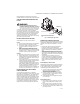
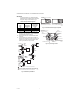
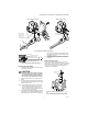
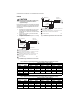

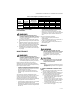

Table Of Contents

VR8300/VR8301 CONTINUOUS PILOT COMBINATION GAS CONTROL
9 69-0624—03
CHECK SAFETY SHUTDOWN
PERFORMANCE
WARNING
FIRE OR EXPLOSION HAZARD CAN CAUSE
PROPERTY DAMAGE, SEVERE INJURY, OR DEATH
Perform the safety shutdown test any time work
is done on a gas system.
1. Place the gas control knob in the PILOT position.
Main burner should go off and pilot should remain
lit.
2. Extinguish pilot flame. Pilot gas flow should stop
within 2-1/2 minutes. Safety shutoff of pilot gas
proves complete shutdown because safety shutoff
valve prevents main burner and pilot gas flow.
3. Relight pilot burner and operate system through
one complete cycle to make sure all controls oper-
ate properly.
MAINTENANCE
WARNING
FIRE OR EXPLOSION HAZARD CAN CAUSE
PROPERTY DAMAGE, SEVERE INJURY, OR DEATH
Improper cleaning or reassembly can cause gas
leakage. When cleaning, be sure that control is
reassembled properly and perform gas leak test.
Regular preventive maintenance is important in
applications such as in the commercial cooking and
agricultural and industrial industries that place a heavy
load on system controls, because:
• In many such applications, particularly commercial
cooking, the equipment operates 100,000 to 200,000
cycles per year. Such heavy cycling can wear out the
gas control in one to two years.
• Exposure to water, dirt, chemicals and heat can
damage the gas control and shut down the control
system.
The maintenance program should include regular
checkout of the gas control as outlined in Start-up and
Checkout section, checkout the control system as
described in the appliance manufacturers literature.
Maintenance frequency must be determined individually
for each application. Some considerations are:
• Cycling frequency. Appliances that may cycle 100,000
times annually should be checked monthly.
• Intermittent use. Appliances that are used seasonally
should be checked before shutdown and again before
the next use.
• Consequence of unexpected shutdown. Where the
cost of an unexpected shutdown would be high, the
system should be checked more often.
• Dusty, wet, or corrosive environment. Since these
environments can cause the gas control to deteriorate
more rapidly, the system should be checked more
often.
The gas control should be replaced if:
• It does not perform properly on checkout or
troubleshooting.
• The gas control knob is hard to turn or push down, or
it fails to pop back up when released.
• The gas control is likely to have operated for more
than 200,000 cycles.
SERVICE
WARNING
FIRE OR EXPLOSION HAZARD CAN CAUSE
PROPERTY DAMAGE, SEVERE INJURY OR DEATH
Do not disassemble the gas control; it contains
no replaceable components. Attempted
disassembly or repair may damage the gas
control.
CAUTION
Do not apply a jumper across or short the valve
coil terminals. Doing so can burn out the heat
anticipator in the thermostat.
IMPORTANT:
Allow 60 seconds after shutdown before reener-
gizing step-opening model to assure lightoff at
step pressure.
IF THE PILOT BURNER FLAME WILL NOT
LIGHT
1. Assure the main gas supply valve is open and the
pilot gas supply line is purged of air.
2. Attempt to light pilot burner flame following proce-
dures in the Lighting the Pilot Burner Flame sec-
tion. If pilot burner flame still will not light:
a. Check the pilot gas adjustment screw. If closed,
readjust the pilot flame. Refer to Adjust the
Pilot Burner Flame section.
b. b. Perform the Gas Leak Test at the compres-
sion fitting. If a gas leak is detected, replace the
old compression fitting or tighten the newly
installed one. Refer to Fig. 4.
c. c. Assure that the pilot burner tubing or pilot
burner orifice is not clogged.
Table 9. Pressure Regulator Specification Pressures in kPa
Model Type of Gas
Nominal Inlet
Pressure Range
Outlet Pressure
Nominal Factory Setting Setting Range
Step Full Rate Step Full Rate
Standard,
slow opening
Natural 1.2 - 1.7 -- 0.9 -- 0.7 - 1.2
LP 2.9 -- 2.7 -- 2.0 - 3.0
Step-
opening
Natural 1.2 - 1.7 0.2 0.9 -- 0.7 - 1.2
LP 2.9 - 3.9 0.9 2.7 -- 2.0 - 3.0