
Install Instructions
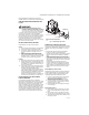
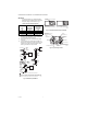
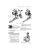
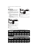

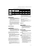

Table Of Contents

VR8300/VR8301 CONTINUOUS PILOT COMBINATION GAS CONTROL
69-0624—03 8
CHECK AND ADJUST GAS INPUT TO MAIN
BURNER
CAUTION
1. Do not exceed the input rating stamped on the
appliance nameplate, or the manufacturers recom-
mended burner orifice pressure for the size ori-
fice(s) used. Make sure the main burner primary air
supply is properly adjusted for complete combus-
tion (refer to the appliance manufacturers instruc-
tions).
2. WHEN CHECKING GAS INPUT BY CLOCKING THE
GAS METER:
— Make sure that the only gas flow through the
meter is that of the appliance being checked.
— Make sure that other appliances are turned off
and that the pilot burners are extinguished (or
deduct the gas consumptions from the meter
reading).
— Convert the flow rate to Btuh as described in the
Gas Controls Handbook, (form 70-2602), and
compare to the Btuh input rating on the appliance
nameplate.
3. WHEN CHECKING GAS INPUT WITH A MANOME-
TER (PRESSURE GAUGE):
— Make sure the gas control knob is in the PILOT
position before removing the outlet pressure tap
plug to connect the manometer.
— Turn the gas control knob back to PILOT when
removing the manometer and replacing the outlet
pressure tap plug.
— Shut off the gas supply at the appliance service
valve or, for LP gas, at the gas tank before remov-
ing the outlet pressure tap plug and before dis-
connecting the manometer and replacing the
outlet pressure tap plug.
Standard-Opening and Slow-Opening
Pressure Regulator
1. The gas control outlet pressure should match the
manifold pressure listed on the appliance name-
plate.
2. With the main burner operating, check the gas con-
trol flow rate using the meter clocking method or
check the gas pressure using a manometer con-
nected to the gas control outlet pressure tap. Refer
to Fig. 4.
3. If necessary, adjust the pressure regulator to
match the appliance rating. Refer to Table 8 or 9 for
the factory set nominal outlet pressures and
adjustment ranges.
a. Remove the pressure regulator adjustment cap
screw.
b. Using a screwdriver, turn the inner adjustment
screw clockwise to increase or counterclock-
wise. to decrease the main burner gas pres-
sure.
c. Always replace the cap screw and tighten
firmly to be sure of proper operation.
4. If the desired outlet gas pressure or gas flow rate
cannot be achieved by adjusting the gas control,
check the gas control inlet pressure using a
manometer at the inlet pressure tap. If the inlet
pressure is in the normal range (refer to Table 8 or
9), replace the gas control. Otherwise, take the nec-
essary steps to provide proper gas pressure to the
gas control.
Step-Opening Pressure Regulator
1. The gas control outlet pressure should match the
manifold pressure listed on the appliance name-
plate.
2. With the main burner operating, check the gas con-
trol flow rate using the meter clocking method or
check the gas pressure using a manometer con-
nected to the gas control outlet pressure tap. Refer
to Fig. 4.
3. If necessary, adjust the pressure regulator to
match the appliance rating. Refer to Table 8 or 9 for
factory set nominal outlet pressures and adjust-
ment ranges.
a. Remove the pressure regulator adjustment cap
screw.
b. Using a screwdriver, turn the inner adjustment
screw clockwise to increase or counterclock-
wise to decrease the main burner gas pressure.
c. Always replace the cap screw and tighten
firmly to safeguard proper operation.
4. If desired outlet pressure or flow rate cannot be
achieved by adjusting the gas control, check the
inlet pressure using a manometer at inlet pressure
tap or upstream of the gas control. If the inlet pres-
sure is in the normal range (refer to Table 8 or 9),
replace the existing gas control. Otherwise, take
the necessary steps to provide proper gas pressure
to the gas control.
5. 5. Carefully check main burner lightoff at the step
pressure. Be sure the main burner lights smoothly
and without flash back to the orifice and that all
ports remain lit. Cycle the main burner several
times, allowing at least 30 seconds between cycles
for the regulator to resume the step function.
Repeat after allowing main burner to cool. Readjust
the full rate outlet pressure, if necessary, to
improve lightoff characteristics.
Table 8. Pressure Regulator Specification Pressures in in. wc.
Model
Nominal Inlet
Pressure Type of Gas
Nominal Inlet
Pressure Range
Outlet Pressure
Nominal Factory Setting Setting Range
Step Full Rate Step Full Rate
Standard,
slow opening
Natural 5.0 - 7.0 -- 3.5 -- 3.0 - 5.0
LP 12.0 - 14.0 -- 11.0 -- 8.0 - 12.0
Step-
opening
Natural 5.0 - 7.0 0.9 3.5 -- 3.0 - 5.0
LP 12.0 - 14.0 2.2 11.0 -- 8.0 - 12.0