
Install Instructions
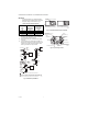
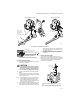
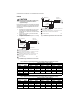

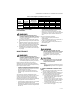

Table Of Contents

VR8300/VR8301 CONTINUOUS PILOT COMBINATION GAS CONTROL
69-0624—03 6
WIRING
CAUTION
Disconnect power supply before making wiring
connections to prevent electrical shock or
equipment damage.
Follow the wiring instructions furnished by the appliance
manufacturer, if available, or use the general instructions.
All wiring must comply with applicable electrical codes
and ordinances.
1. Check the power supply rating on the gas control
and make sure it matches the available supply.
Install transformer, thermostat, and other controls
as required.
2. Connect control circuit to gas control terminals.
See Figs. 4, 8, and 9.
3. 3. Adjust thermostat heat anticipator to 0.70 rating
stamped on valve operator.
Fig. 8. VR8300 wiring connections for 24 volt control.
Fig. 9. VR8301 wiring connections for 24 volt control.
L1
(HOT)
L2
1
24 V
THERMOSTAT
OPTIONAL
CONVENIENCE
TERMINALS
TH/TR
TH
TR
VR8300 TERMINALS
HIGH LIMIT
CONTROLLER
POWER SUPPLY. PROVIDE DISCONNECT MEANS AND OVERLOAD
PROTECTION AS REQUIRED.
DO NOT JUMPER THESE TERMINALS. THIS SHORTS VALVE COIL
AND MAY BURN OUT ANTICIPATOR IN THERMOSTAT.
CONVENIENCE TERMINALS SERVE AS A TIE POINT ONLY. THEY
ARE NOT INTERNALLY WIRED TO THE CONTROL CIRCUIT
OR TO GROUND.
OPTIONAL HIGH LIMIT.
1
2
3
4
2
3
4
M8581
L1
(HOT)
L2
1
24 V
THERMOSTAT
MV/PV
PV
VR8301
TERMINALS
HIGH LIMIT
CONTROLLER
POWER SUPPLY. PROVIDE DISCONNECT MEANS AND OVERLOAD
PROTECTION AS REQUIRED.
DO NOT JUMPER THESE TERMINALS. THIS SHORTS VALVE COIL
AND MAY BURN OUT ANTICIPATOR IN THERMOSTAT.
OPTIONAL HIGH LIMIT.
1
2
3
2
3
M8580
MV
Table 6. Maximum Length of Supplementary Limit Leadwires When Using Q340A Thermocouple
Thermocouple Length
Maximum Leadwire Length x 2 (Wires)
Awg No. 14 Awg No. 16 Awg No. 18
Inches Meters Inches Meters Inches Meters Inches Meters
18 0.5 0.35 0.9 22 0.6 13 0.3
24 0.6 0.29 0.7 18 0.5 11 0.3
30 0.8 0.23 0.6 15 0.4 9 0.2
36 0.9 0.17 0.4 11 0.3 6 0.2
48 1.2
DO NOT USE
60 1.5
Table 7. Maximum Length of Supplementary Limit Leadwires When Using Q309A Thermocouple
Thermocouple Length
Maximum Leadwire Length x 2 (Wires)
Awg No. 14 Awg No. 16 Awg No. 18
Inches Meters Inches Meters Inches Meters Inches Meters
12 0.3 47 1.2 30 0.8 18 0.5
18 0.5 41 1.0 26 0.7 16 0.4
24 0.6 35 0.9 22 0.6 14 0.4
30 0.8 29 0.8 18 0.5 11 0.3