
Install Instructions
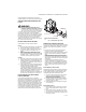
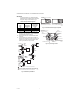
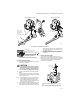
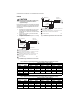

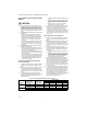

Table Of Contents

VR8300/VR8301 CONTINUOUS PILOT COMBINATION GAS CONTROL
69-0624—03 4
IMPORTANT:
Do not thread pipe too far. Valve distortion or
malfunction may result if the pipe is inserted too
deeply into the gas control. Refer to Fig. 3.
4. Apply a moderate amount of good quality pipe
compound (do not use Teflon tape) to pipe only,
leaving two end threads bare. On LP installations,
use compound resistant to LP gas.
5. Remove seals over gas control inlet and outlet if
necessary.
6. Connect pipe to gas control inlet and outlet. Use
wrench on the square ends of the gas control. If an
adapter is used, place wrench on adapter rather
than on gas control. See Figs. 4 and 5.
Fig. 2. Sediment trap installation.
Fig. 3. Use moderate amount of pipe compound.
Fig. 4. Top view of gas control.
Table 5. NPT Pipe Thread Length in in.
Pipe
Size
Thread Pipe
This Amount
Maximum Depth
Pipe Can Be
Inserted Into
Control
3/8 9/16 3/8
1/2 3/4 1/2
3/4 13/16 3/4
GAS
CONTROL
GAS
CONTROL
HORIZONTAL
DROP
PIPED
GAS
SUPPLY
PIPED
GAS
SUPPLY
3 INCHES
[76]
MINIMUM
3 INCHES
[76]
MINIMUM
RISER
GAS
CONTROL
TUBING
GAS
SUPPLY
HORIZONTAL
DROP
3 INCHES
[76]
MINIMUM
RISER
M3077
2
1
2
2
1
2
ALL BENDS IN METALLIC TUBING SHOULD BE SMOOTH.
CAUTION: SHUT OFF THE MAIN GAS SUPPLY BEFORE REMOVING
END CAP TO PREVENT GAS FROM FILLING THE WORK AREA. TEST
FOR GAS LEAKAGE WHEN INSTALLATION IS COMPLETE.
TWO IMPERFECT
THREADS
GAS CONTROL
THREAD PIPE THE AMOUNT
SHOWN IN TABLE 4 FOR
INSERTION INTO GAS CONTROL
APPLY A MODERATE AMOUNT OF
PIPE COMPOUND TO PIPE ONLY
(LEAVE TWO END THREADS BARE).
M3075A
PIPE
OUTLET
PRESSURE
TAP
INLET
OUTLET
WIRING
TERMINALS (3)
INLET
PRESSURE TAP
PRESSURE REGULATOR
ADJUSTMENT
(UNDER CAP SCREW)
PILOT OUTLET
PILOT ADJUSTMENT
(UNDER CAP SCREW)
GAS
CONTROL
KNOBRED RESET BUTTON
M1639C