
Install Instructions
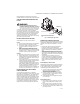
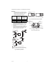
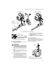
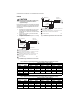

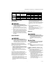

Table Of Contents

VR8300/VR8301 CONTINUOUS PILOT COMBINATION GAS CONTROL
69-0624—03 2
NOTE: Flange kits include one flange with attached O-ring and fan mounting screw.
Approvals:
American Gas Association Design Certificate: UP-70-
69A.
Canadian Gas Association Design Certificate: UP-70-
69A.
Australian Gas Association Certificate: Applied for.
Delta C: Applied for.
INSTALLATION
WHEN INSTALLING THIS
PRODUCT…
1. Read these instructions carefully. Failure to follow
them could damage the product or cause a hazard-
ous condition.
2. Check the ratings given in the instructions and on
the product to assure the product is suitable for
your application.
3. Assure installer is a trained, experienced service
technician.
4. After installation is complete, use these instruc-
tions to check out product operation.
WARNING
FIRE OR EXPLOSION HAZARD CAN CAUSE
PROPERTY DAMAGE, SEVERE INJURY, OR DEATH
Follow these warnings exactly.
1. Disconnect power supply before wiring to
prevent electrical shock or equipment damage.
2. To avoid dangerous accumulation of fuel gas,
turn off gas supply at the appliance service
valve before starting Installation, and perform
Gas Leak Test after completion of Installation.
3. Do not bend the pilot tubing at the gas control
or pilot burner after compression fitting has
been tightened, or gas leakage at the
connection may result.
4. Always install sediment trap in gas supply line
to prevent contamination of gas control.
5. Do not force the gas control knob. Use only
your hand to push down the reset button or
turn the gas control knob. Never use any tools.
If the gas control knob or reset button will not
operate by hand, to replace the gas control,
contact a qualified service technician. Force or
attempted repair may result in fire or explosion.
CAUTION
Never apply a jumper across or short the valve
coil terminals. This may burn out the heat
anticipator in the thermostat.
IMPORTANT:
These gas controls are shipped with protective
seals over inlet and outlet tappings. Do not
remove seals until ready to connect piping.
Table 2. Gas Capacity Conversion Factors
Gas Specific Gravity Multiply Listed Capacity By
Manufactured 0.60 0.516
Mixed 0.70 0.765
Propane 1.53 1.62
Table 3. Temperature Ranges and Regulator Types
Model Number Ambient Temperature Range Regulator Type
VR8300A 0° F to 175° F [-18° C to +79° C] Standard-opening
VR8300C 0° F to 175° F [-18° C to +79° C] Step-opening
VR8300H 0° F to 175° F [-18° C to +79° C] Slow-opening
VR8300K -40° F to 175° F [-40° C to +79° C] Slow-opening
VR8300M -40° F to 175° F [-40° C to +79° C] Standard-opening
VR8300P -40° F to 175° F [-40° C to +79° C] Step-opening
VR8301 0° F to 175° F [-18° C to 79° C] Standard-opening
Table 4. Flange Part Numbers
Inlet/Outlet Pipe Size Flange Type
Part Number
Without Hex Wrench With Hex Wrench
1/2 inch NPT
Straight 394599-6 393690-16
Elbow 394599-3 393690-13
3/4 inch NPT
Straight 394599-4 393690-14
Elbow 394599-5 393690-15