
Install Instructions
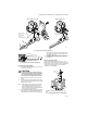
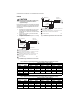

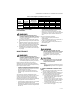

Table Of Contents

INSTALLATION INSTRUCTIONS
69-0624-03
VR8300/VR8301 Continuous Pilot
Combination Gas Control
APPLICATION
These continuous pilot gas controls are used in gas-fired appliances with capacities up to 200 cu ft/hour at 1 in. wc
pressure drop [5.7 cu m/hour at 0.25 kPa] on natural gas. They include a manual valve, safety shutoff, single
automatic operators, and a pressure regulator. See Table 3 for temperature ranges and regulator types.
Body Pattern:
Straight-through body pattern.
Inlet x Outlet Sizes Available:
1/2 x 1/2 in., 1/2 x 3/4 in., and 3/4 x 3/4 in. (factory-installed inlet flange).
Adapters:
Adapters available for 1/2 and 3/4 inch straight and angle connections. Refer to Table 4.
Electrical Ratings:
Voltage and Frequency: 24 Vac, 50/60 Hz.
Current Draw: 0.70A.
Capacity:
See Table 1.
a
Capacity based on 1000 Btu/cu ft, 0.64 specific gravity natural gas at 1 in. wc pressure drop [37.3 MJ/cu m, 0.64
specific gravity natural gas at 0.25 kPa pressure drop.
Use conversion factors in Table 2 to convert capacities for other gases.
Table 1. Capacity of VR8300/VR8301
Size
(Inlet x Outlet)
Capacity (at 1 in. wc
pressure drop)
a
Minimum
Regulated Capacity
Maximum
Regulated Capacity
1/2 x 1/2 180 cu ft/hr
[5.1 cu m/hr]
30 cu ft/hr
[0.8 cu m/hr]
225 cu ft/hr
[6.4 cu m/hr]
1/2 x 3/4 190 cu ft/hr
[5.4 cu m/hr]
30 cu ft/hr
[0.8 cu m/hr]
290 cu ft/hr
[8.2 cu m/hr]
3/4 x 3/4 200 cu ft/hr
[5.7 cu m/hr]
30 cu ft/hr
[0.8 cu m/hr]
300 cu ft/hr
[8.5 cu m/hr]