
Install Instructions
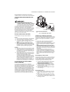
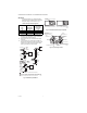

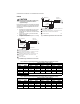
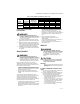
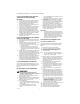
Table Of Contents

VR8300/VR8301 CONTINUOUS PILOT COMBINATION GAS CONTROL
7 69-0624—03
START-UP AND CHECKOUT
WARNING
FIRE OR EXPLOSION HAZARD CAN CAUSE
PROPERTY DAMAGE, SEVERE INJURY, OR DEATH
1. Do not force the gas control knob. Use only
your hand to push down the reset button or
turn the gas control knob. Never use any tools.
2. If the gas control knob or reset button will not
operate by hand, or if the reset button stays
depressed after it is released, to replace the
gas control call a qualified service technician.
GAS CONTROL KNOB SETTINGS
The gas control knob has three settings:
OFF: Prevents pilot and main burner gas flow.
PILOT: Permits pilot gas flow only. Gas control knob must
be held depressed or the thermocouple must be heated
sufficiently to hold the safety control valve open.
ON: Permits main burner and pilot gas flow. Gas control
and thermostat control main burner gas flow.
NOTE: Gas controls are shipped with the gas control
knob in the ON position.
PERFORM GAS LEAK TEST
WARNING
FIRE OR EXPLOSION HAZARD CAN CAUSE
PROPERTY DAMAGE, SEVERE INJURY, OR DEATH
Check for gas leaks with rich soap and water
solution any time work is done on a gas control.
GAS LEAK TEST
1. Paint all pipe connections upstream of the gas
control with a rich soap and water solution. Bub-
bles indicate a gas leak.
2. If a gas leak is detected, tighten the pipe connec-
tion.
CAUTION
Stand clear while lighting main burner to prevent
injury caused from hidden gas leaks that could
cause flashback in the appliance vestibule.
3. Light the main burner.
4. With the main burner in operation, paint all pipe
joints (including adapters) and gas control inlet
and outlet with rich soap and water solution.
5. If another gas leak is detected, tighten adapter
screws, joints, and pipe connections.
6. If gas leak cannot be stopped, turn the gas control
knob clockwise to off.
7. Replace the leaking part.
8. Perform the gas leak test.
LIGHT THE PILOT BURNER FLAME
1. Turn the gas control knob clockwise to OFF. Wait
five minutes to dissipate any unburned gas. Sniff
around the appliance near the floor. Do not relight
the pilot flame if you smell gas.
2. Turn the gas control knob counterclockwise to
PILOT. Push down and hold the gas control knob
while lighting the pilot flame.
3. Hold the gas control knob down about one minute,
then release.
• If the pilot flame goes out, turn the gas control knob
clockwise to OFF and repeat steps one through three.
• If pilot flame remains lit, turn the gas control knob
counterclockwise to ON.
ADJUST THE PILOT BURNER FLAME
The pilot flame should envelop 3/8 to 1 /2 in. [10 to 13
mm] of the thermocouple tip. Refer to Fig. 10. To adjust
the pilot flame:
1. Remove the pilot adjustment cover screw. Refer to
Fig. 5.
2. Turn the inner adjustment screw clockwise, to
decrease or counterclockwise to increase the pilot
flame.
3. Be sure to replace the cover screw after adjust-
ment and tighten firmly.
LIGHT MAIN BURNER
Follow the appliance manufacturer instructions or set the
thermostat setting above room temperature to call for
heat.
Fig. 10. Proper flame adjustment.
36 0.9 23 0.6 15 0.4 9 0.2
40 1.0 19 0.5 12 0.3 7 0.2
48 1.2 11 0.3 7 0.2
DO NOT USE
60 1.5 DO NOT USE
Table 7. Maximum Length of Supplementary Limit Leadwires When Using Q309A Thermocouple
Thermocouple Length
Maximum Leadwire Length x 2 (Wires)
Awg No. 14 Awg No. 16 Awg No. 18
Inches Meters Inches Meters Inches Meters Inches Meters
M3086A
PROPER FLAME
ADJUSTMENT
3/8 TO 1/2 INCH
[10 TO 13 MILLIMETERS]
THERMOCOUPLE