
Install Instructions
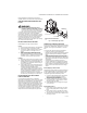
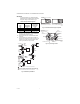

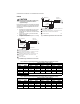
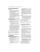
Table Of Contents

VR8300/VR8301 CONTINUOUS PILOT COMBINATION GAS CONTROL
3 69-0624—03
Follow the appliance manufacturers instructions if
available; otherwise, use the instructions provided below.
CONVERTING BETWEEN NATURAL AND
LP GAS
WARNING
FIRE OR EXPLOSION HAZARD CAN CAUSE
PROPERTY DAMAGE, SEVERE INJURY, OR DEATH
Do not use a gas control set for natural gas on LP
gas or a gas control set for LP gas on natural gas.
To convert a gas control from natural gas to LP gas or
from LP gas to natural gas, contact your Resideo
representative. Standard- or slow-opening gas controls
are converted from one gas to another with a conversion
kit (ordered separately). Order part number 393691 to
convert from natural to LP gas. Order part number
394588 to convert from LP to natural gas. Step-opening
gas controls cannot be converted.
INSTALL ADAPTERS TO CONTROL
Install adapters on the gas control as follows:
Flanges
1. Choose the appropriate flange for your application.
2. Remove seal over gas control inlet or outlet.
3. Assure the O-ring fits in the flange groove. If the O-
ring is not attached or is missing, do not use
flange.
4. With O-ring facing gas control, align the screw
holes on the gas control with the holes in the
flange. Insert and tighten the screws provided with
the flange. See Fig. 1. Tighten the screws to 25 inch
pounds of torque to provide a gas-tight seal.
Bushings:
1. Remove the seal over the gas control inlet or outlet.
2. Apply moderate amount of good quality pipe com-
pound to bushing, leaving two end threads bare. On
LP installation, use compound resistant to LP gas.
Do NOT use Teflon tape.
3. Insert bushing in gas control and thread pipe care-
fully into the bushing until tight. Complete instruc-
tions below for piping, installing control,
connecting pilot tubing, thermocouple and wiring.
Make certain the leak test you perform on the con-
trol after completing the installation includes leak
testing the adapters and screws. If you use a
wrench on the valve after flanges are installed, use
the wrench only on the flange, not on the control.
USING ADAPTERS TO SOLVE SWING
RADIUS PROBLEMS
In some field service applications, it is difficult or
impossible to thread the gas control onto the gas supply
pipe because of space limitations. This problem can be
resolved in many instances by using an adapter. The
adapter is installed on the end of the supply pipe in place
of the gas control, following the same precautions and
instructions that are used for installing the gas control.
After the adapter is installed, the gas control is attached
to the adapter as outlined above. Note that using an
adapter increases the overall length of the gas control.
Fig. 1. Install flange to gas control.
CHOOSE GAS CONTROL LOCATION
Do not locate the gas control where it may be affected by
steam cleaning, high humidity, dripping water, corrosive
chemicals, dust or grease accumulation, or excessive
heat.
To assure proper operation, follow these guidelines:
• Locate gas control in a well-ventilated area.
• Mount the gas control high enough above the cabinet
bottom to avoid exposure to flooding or splashing
water.
• Assure the ambient temperature does not exceed the
ambient temperature ratings for each component.
• Cover the gas control if the appliance is cleaned with
water, steam, or chemicals or to avoid dust and grease
accumulation.
• Avoid locating gas control where exposure to
corrosive chemical fumes or dripping water is likely.
Locate the gas control in the appliance vestibule on
the gas manifold. In replacement applications, locate
the gas control in the same location as the old gas
control.
Install Piping to Gas Control
All piping must comply with local codes and ordinances
or with the National Fuel Gas Code (ANSl Z223.1 NFPA
No. 54), whichever applies. Tubing installation must
comply with approved standards and practices.
1. Use new, properly reamed pipe free from chips. If
tubing is used, assure the ends are square,
deburred and clean. All tubing bends must be
smooth and without deformation.
2. Run pipe or tubing to the gas control. If tubing is
used, obtain a tube-to-pipe coupling to connect
the tubing to the gas control.
3. Install sediment trap in the supply line to the gas
control. See Fig. 2.
Install Gas Control
1. Mount the gas control 0-90 degrees, in any direc-
tion from the upright position of the gas control
knob.
2. Mount the gas control so gas flow is in the direc-
tion of the arrow on the bottom of the gas control.
3. Thread pipe the amount shown in Table 5 for inser-
tion into gas control.
M3087
GAS CONTROL OUTLET
FLANGE
9/64 INCH HEX
SCREWS (4)
1 DO NOT OVERTIGHTEN SCREWS.
TIGHTEN TO 25 INCH POUNDS.
1