
Install Instructions


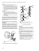
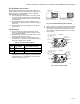
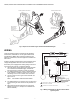
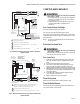
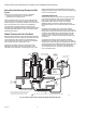
Table Of Contents

VR8205; VR4205 DIRECT IGNITION DUAL AUTOMATIC VALVE COMBINATION GAS CONTROLS
68-0049—03 6
Fig. 6. Proper use of wrench on gas control with and without flanges.
WIRING
Follow the wiring instructions furnished by the appliance
manufacturer, if available, or use the general instructions
provided below. Where these instructions differ from the
appliance manufacturer, follow the appliance manufacturer
instructions.
All wiring, including insulated quick connect terminals, must
comply with applicable electrical codes and ordinances.
Disconnect power supply before making wiring connections
to prevent electrical shock or equipment damage.
1. Check the power supply rating on the valve and make
sure it matches the available supply. Install trans-
former, thermostat, and other controls as required.
2. For VR4205, when the gas control is installed external
to the appliance, install the conduit cover on the con-
duit fitting. Do not secure conduit cover at this time.
3. Connect control circuit to gas control terminals. See
Fig. 5 and 7-9.
NOTE: Use leadwires with insulated terminals.
4. For VR4205, make sure conduit cover is in position and
secured to the gas valve with the screw provided. See
Fig. 2.
5. Adjust thermostat heat anticipator as instructed in
appliance manual (i.e., usually 0.1A for VR4205 and
0.5A for VR8205).
Fig. 7. Wiring connections for 120 volt control in direct
ignition system.
APPLY WRENCH
TO FLANGE ONLY
WHEN FLANGE IS USED
APPLY WRENCH
FROM TOP OR
BOTTOM OF GAS
CONTROL TO
EITHER SHADED AREA
WHEN FLANGE IS NOT USED
M3079C
IGNITION MODULE
L1
(HOT)
L2
LIMIT CONTROLLER
Q347 IGNITER-SENSOR
120V (GND)
VALVE
VALVE
GND
POWER SUPPLY. PROVIDE DISCONNECT MEANS AND OVERLOAD
PROTECTION AS REQUIRED.
ALTERNATE LIMIT CONTROLLER LOCATION.
M3090B
BURNER
120V
VR4205
DUAL VALVE
COMBINATION
GAS CONTROL
L2
L1
1
2
1
2