
Install Instructions
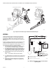
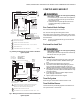
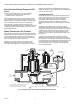
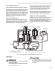
Table Of Contents

VR8205; VR4205 DIRECT IGNITION DUAL AUTOMATIC VALVE COMBINATION GAS CONTROLS
11 68-0049—03
Slow-Opening Regulation
Slow-opening gas controls function the same as standard
models except that when the thermostat calls for heat, the
second automatic valve opens gradually. Opening is slowed
because a flow restructure in the passage from the second
automatic operator slows the rate at which gas pressure is
reduced under the second automatic valve diaphragm after
the second automatic operator opens. Outlet pressure to the
main burner increases gradually from 0 in. wc [0 kPa] to rated
output pressure within 3-6 seconds (for an 80,000 Btuh
furnace at 7 in. wc [1.8 kPa] inlet pressure and 3.5 in. wc
[0.9 kPa] outlet pressure).
Step-Opening Regulation
Step-opening gas controls actually combine two pressure
regulators, one for the low pressure and one for the full-rate
pressure. When the thermostat calls for heat, the automatic
operator valve disc opens. The low pressure regulator
maintains outlet pressure at the preset step rate for
several seconds. Then the regulator valve is forced fully open
by the timing diaphragm, which is operated by bleed gas.
When the low pressure regulator is fully open, the high
pressure regulator maintains the desired full-rate outlet
pressure as described for the standard regulator.
The step model requires approximately 60 seconds to reset
once the main burner goes off. If it is reenergized within 60
seconds, it may bypass or shorten the length of the low
pressure step. The burner may relight at the full flow rate.
When The Call For Heat Ends
When the call for heat ends, the first automatic valve and the
second automatic valve operator close, bypassing the
regulator(s) and shutting off the main burner and the pilot. As
pressure inside the gas control and underneath the
automatic valve diaphragm equalizes, spring pressure closes
the second automatic valve to provide a second barrier to
gas flow.
Fig. 11. Position of gas control components during burner on cycle.
SERVICE
WARNING
Fire or explosion hazard. Can cause property damage,
severe injury, or death.
Do not disassemble the gas control; it contains no
replaceable components. Attempted disassembly or
repair may damage the control..
CAUTION
Do not apply a jumper across (or short) the valve coil
terminals, even temporarily. Doing so may burn out
the heat anticipator in the thermostat or damage the
DI module.
FIRST
AUTOMATIC
VALVE
SOLENOID
CONTROL
KNOB
GAS
CONTROL
INLET
SECOND AUTOMATIC
VALVE OPERATOR
SECOND
AUTOMATIC
OPERATOR
SOLENOID
SECOND
AUTOMATIC
OPERATOR
VALVE DISC
SERVO PRESSURE
REGULATOR
GAS
CONTROL
OUTLET
SECOND AUTOMATIC
VALVE DIAPHRAGM
FIRST AUTOMATIC VALVE
NOTE: SECOND AUTOMATIC VALVE OPERATOR AND
SERVO PRESSURE REGULATOR SHOWN OUTSIDE
GAS CONTROL FOR EASE IN TRACING GAS FLOW.
SLOW-OPENING GAS CONTROL HAS A GAS FLOW RESTRICTOR IN THIS PASSAGE.
M9115A
1
1