
Install Instructions
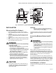
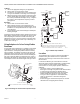
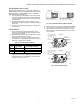

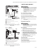
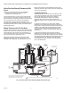
Table Of Contents

VR8205; VR4205 DIRECT IGNITION DUAL AUTOMATIC VALVE COMBINATION GAS CONTROLS
68-0049—03 4
FLANGES:
1. Choose the appropriate flange for your application.
2. Remove seal over control inlet or outlet.
3. Assure the O-ring is fitted in the groove of flange. If the
O-ring is not attached or is missing, do not use flange.
4. With O-ring facing control, align the screw holes on the
control with the holes in the flange. Insert and tighten
the screws provided with the flange. See Fig. 2. Tighten
the screws to 25 inch pounds of torque to provide a
gas-tight seal.
BUSHINGS:
1. Remove seal over control inlet or outlet.
2. Apply moderate amount of good quality pipe com-
pound to bushing, leaving two end threads bare. On LP
installation, use compound resistant to LP gas. Do not
use Teflon tape.
3. Insert bushing in control and thread pipe carefully into
bushing until tight.
Complete instructions below for piping, installing control, and
wiring. Make certain the leak test you perform on the control
after completing the installation includes leak testing the
adapters and screws. If you use a wrench on the valve after
flanges are installed, use the wrench only on the flange, not
on the control. See Fig. 6.
Using Adapters to Solve Swing Radius
Problems
In some field service applications, it is difficult or impossible
to thread the control onto the gas supply pipe because of
space limitations. Usually this problem can be resolved by
using an adapter. The adapter is installed on the end of the
supply pipe in place of the gas control, following the same
precautions and instructions that are used for installing the
gas control. After the adapter is installed, the gas control is
attached to the adapter as outlined above. Note that the use
of an adapter increases the overall length of the gas control.
Fig. 2. Fasten flange to control with 25 inchpounds torque.
Fig. 3. Sediment trap installation.
Location
The combination gas control is mounted in the appliance
vestibule on the gas manifold. If this is a replacement
application, mount the gas control in the same location as
the old control.
Locate the combination gas control where it cannot be
affected by steam cleaning, high humidity, or dripping water,
corrosive chemicals, dust or grease accumulation or
excessive heat. To assure proper operation, follow these
guidelines:
• Locate gas control in a well-ventilated area.
• Mount gas control high enough above the cabinet bottom
to avoid exposure to flooding or splashing water.
• Assure the ambient temperature does not exceed the
ambient temperature ratings for each component.
• Cover gas control if appliance is cleaned with water,
steam, or chemicals or to avoid dust and grease
accumulation.
• Avoid locating gas control where exposure to corrosive
chemical fumes or dripping water are likely.
M9055A
VALVE OUTLET
FLANGE
9/64 INCH HEX SCREWS (4)
6/32 INCH ROUND
SCREWS (1)
CONDUIT
COVER,
VR4205
ONLY
DO NOT OVERTIGHTEN SCREWS. TIGHTEN TO 25 INCH-POUNDS.
1
1
GAS
CONTROL
GAS
CONTROL
HORIZONTAL
DROP
PIPED
GAS
SUPPLY
PIPED
GAS
SUPPLY
3 IN.
(76 MM)
MINIMUM
3 IN.
(76 MM)
MINIMUM
RISER
GAS
CONTROL
TUBING
GAS
SUPPLY
HORIZONTAL
DROP
3 IN.
(76 MM)
MINIMUM
RISER
M3077D
2
1
2
2
1
2
ALL BENDS IN METALLIC TUBING SHOULD BE SMOOTH.
CAUTION: SHUT OFF THE MAIN GAS SUPPLY BEFORE REMOVING
END CAP TO PREVENT GAS FROM FILLING THE WORK AREA. TEST
FOR GAS LEAKAGE WHEN INSTALLATION IS COMPLETE.