
Install Instructions
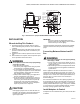
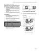

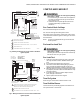
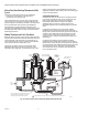
Table Of Contents

VR8205; VR4205 DIRECT IGNITION DUAL AUTOMATIC VALVE COMBINATION GAS CONTROLS
3 68-0049—03
Fig. 1. Dimensions in in. [mm] of VR4205/VR8205 Combination Gas Control.
INSTALLATION
When Installing This Product…
1. Read these instructions carefully. Failure to follow
them could damage the product or cause a hazardous
condition.
2. Check the ratings given in the instructions and on the
product to make sure the product is suitable for your
application.
3. Installer must be a trained, experienced service techni-
cian.
4. After installation is complete, check out product opera-
tion as provided in these instructions.
WARNING
Fire or explosion hazard. Can cause property damage,
severe injury, or death.
Follow these warnings exactly:
1. Disconnect power supply before wiring to prevent
electrical shock or equipment damage.
2. To avoid dangerous accumulation of fuel gas, turn
off gas supply at the appliance service valve before
starting installation, and perform Gas Leak Test
after completion of installation.
3. Always install sediment trap in gas supply line to
prevent contamination of gas control.
4. Do not force the gas control knob. Use only your
hand to turn the gas control knob. Never use any
tools. If the gas control knob will not operate by
hand, the gas control should be replaced by a
qualified service technician. Force or attempted
repair may result in fire or explosion.
CAUTION
Never apply a jumper across or short the valve coil
terminals. This may burn out the heat anticipator in
the thermostat or damage the electronic direct
ignition (DI) module.
IMPORTANT:
These gas controls are shipped with protective
seals over inlet and outlet tappings. Do not remove
seals until ready to connect piping.
Follow the appliance manufacturer instructions if available;
otherwise, use the instructions provided on the following
pages.
Converting Between Natural and LP
Gas
WARNING
Fire or explosion hazard. Can cause property damage,
severe injury, or death.
1. Do not use a gas control set for natural gas on an
LP gas system or a gas control set for LP gas on a
natural gas system.
2. When making conversion, main pilot burner orifices
must be changed to meet appliance manufacturer
specifications.
Refer to appliance manufacturer instructions for orifice
specifications and changeover procedure. Gas controls are
factory-set for natural (and manufactured) or LP gas. Do not
attempt to use a control set for natural (and manufactured)
gas on LP gas, or a control set for LP on natural (and
manufactured) gas.
Gas controls with standard or slow-opening regulators can
be converted from one gas to the other with a conversion kit
(ordered separately). Order part no. 393691 to convert from
natural (and manufactured) to LP gas; order part no. 394588
to convert from LP to natural (manufactured) gas. Controls
with step-opening regulators cannot be converted.
Install Adapters to Control
If adapters are to be installed on the gas control, mount them
as follows:
M9062A
3-1/2
(89)
2-11/16 (69)
1 (25)
1/2
(13)
3-5/8 (91)
SWING
RADIUS
CONDUIT COVER (VR4205 ONLY)
1 (25)
1/2
(13)
(FOR FLANGE
MOUNTING)
8-32
TAPPED [4]
4-1/8 (104)
1-1/8
(28)