
Install Instructions
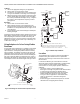

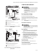
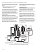
Table Of Contents

VR8205; VR4205 DIRECT IGNITION DUAL AUTOMATIC VALVE COMBINATION GAS CONTROLS
68-0049—03 10
Valve Position During Thermostat Off
Cycle
The valve is positioned as shown in Fig. 10 when the:
• manual gas control knob is in the ON position.
• thermostat is not calling for heat.
The first automatic valve is closed. The second automatic
valve operator is de-energized, closing the channel to the
pressure regulator, and opening a channel to the underside of
the second automatic valve operator valve diaphragm.
The combination of spring pressure under the second
automatic valve diaphragm and lack of outlet pressure holds
the diaphragm firmly closed. Gas flow to the main burner is
blocked by both valves.
When Thermostat Calls For Heat
When the thermostat calls for heat, the DI module generates
a spark at the main burner and the first automatic valve and
second automatic valve operators are energized (Fig. 11).
The first automatic valve opens, and the second automatic
valve operator valve disc is lifted off its seat.
This diverts gas flow from the second automatic valve
diaphragm, and causes a reduction of pressure on the
underside of this diaphragm. The reduced pressure on the
bottom of the automatic valve diaphragm repositions the
diaphragm downward, away from the valve seat, allowing gas
to flow to the main burner.
Standard Regulation
During the ON cycle, the servo pressure regulator provides
close control of outlet pressure, even if inlet pressure and
flow rate vary widely. Any outlet pressure change is
immediately reflected back to the pressure regulator
diaphragm, which repositions to change the flow rate
through the regulator valve, and thus through the automatic
valve.
If outlet pressure begins to rise, the pressure regulator
diaphragm moves slightly higher, allowing less gas flow to
the gas control outlet. This increases gas pressure under the
automatic valve diaphragm and repositions the valve disc
closer to the seat. Thus, flow of gas through the second
automatic valve is reduced, and outlet pressure falls to the
desired level.
If outlet pressure begins to fall, the pressure regulator
diaphragm moves slightly lower, allowing more gas flow to
the gas control outlet. This decreases gas pressure under the
second automatic valve diaphragm and repositions the valve
disc further from the seat. Thus, flow of gas through the
second automatic valve is increased. and outlet pressure
rises to the desired level.
Fig. 10. Position of gas control components during thermostat off cycle.
FIRST
AUTOMATIC
VALVE
SOLENOID
CONTROL
KNOB
GAS
CONTROL
INLET
SECOND AUTOMATIC
VALVE OPERATOR
SECOND
AUTOMATIC
OPERATOR
SOLENOID
SECOND
AUTOMATIC
OPERATOR
VALVE DISC
SERVO PRESSURE
REGULATOR
GAS
CONTROL
OUTLET
SECOND AUTOMATIC
VALVE DIAPHRAGM
FIRST AUTOMATIC VALVE
NOTE: AUTOMATIC VALVE OPERATOR AND SERVO
PRESSURE REGULATOR SHOWN OUTSIDE GAS
CONTROL FOR EASE IN TRACING GAS FLOW.
SLOW-OPENING GAS CONTROL HAS A GAS FLOW RESTRICTOR IN THIS PASSAGE.
M9114B
1
1