
Install Instructions


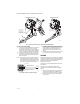
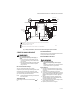
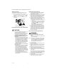
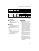
Table Of Contents

VR8204A,M INTERMITTENT PILOT COMBINATION GAS CONTROL
7 69-0423—04
SERVICE
WARNING
Fire or Explosion Hazard
Can cause property damage, severe injury, or
death.
Do not take this control apart; it contains no
replaceable components. Attempts disassembly
or repair may damage the control.
CAUTION
Do not apply a jumper across (or short) the valve
coil terminals, even temporarily. Doing so may
burn out the heat anticipator in the thermostat or
damage the electronic module.
If Main Burner Will not Come On with Call
for Heat
1. Confirm that the gas control knob is in the ON posi-
tion.
2. Adjust the thermostat several degrees above room
temperature.
3. Using ac voltmeter, check for 24 V at gas control.
• If pilot lights, measure across MV/PV and MV.
• If pilot does not light, measure across MV/PV
and PV before safety lockout occurs.
4. If voltage is incorrect or not present, check control
circuit for proper operation.
5. If 24 V is present, replace gas control.
Instructions To The Homeowner (For
Your Safety, Read Before Operating)
WARNING
Fire or Explosion Hazard
Can cause property damage, severe injury, or
death.
Follow the warnings below and the lighting
instructions exactly.
1. Before lighting, smell all around the appliance
area for gas. If the appliance uses LP (Bottled
gas, also be sure to smell next to the floor
because LP gas is heavier than air. If you smell
gas, immediately shut off the manual valve in
the gas piping to the appliance or, ON LP, AT
THE TANK. DO NOT TRY TO LIGHT ANY
APPLIANCE. Don’t touch any electrical switch
or use the phone. LEAVE THE BUILDING and
call your gas supplier. If your gas supplier
cannot be reached, call the fire department.
2. Do not force the gas control knob on the
appliance. Use only your hand to turn the gas
control knob. Never use any tools. If the knob
will not operate by hand, the control should be
replaced by a qualified service technician.
Force or attempted repair may result in fire or
explosion.
3. The gas control must be replaced if it has been
flooded with water. Call a qualified service
technician.
4. The gas control is a safety device. It must be
replaced in case of any physical damage such
as bent terminals, missing or broken parts,
stripped threads or evidence of exposure to
heat.
IMPORTANT:
Follow the operating instructions provided by
manufacturer of you heating appliance. The
information below will be of assistance in a typ-
ical control application, but the specific controls
used and the procedures outlined by the manu-
facturer of your appliance may differ, requiring
special instructions.
Table 3. Pressure Regulator Specification Pressures in Inches WC.
Model Type of Gas
Nominal Inlet
Pressure Range
Outlet Pressure
Nominal Factory Outlet Setting Adjustment Setting Range
Step Full Rate Step Full Rate
Standard Natural 5.0 - 7.0 — 3.5 — 3.0 - 5.0
LP 12.0 - 14.0 — 10.0 — 8.0 - 12.0
Table 4. Pressure Regulator Specification Pressures in kPa.
Model Type of Gas
Nominal Inlet
Pressure Range
Outlet Pressure
Nominal Factory Outlet Setting Adjustment Setting Range
Step Full Rate Step Full Rate
Standard Natural 1.2 - 1.7 — 0.9 — 0.7 - 1.2
LP 2.9 - 3.9 — 2.7 — 2.0 - 3.0