
Install Instructions


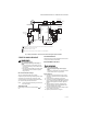
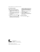
Table Of Contents

VR8204A,M INTERMITTENT PILOT COMBINATION GAS CONTROL
69-0423—04 6
Adjust Pilot Flame
The pilot flame should envelop 3/8 to 1/2 in. [10 to
13 mm] of the tip of the igniter-sensor. See Fig. 8.
1. Remove pilot adjustment screw clockwise to
decrease or counterclockwise to increase
pilot flame.
2. Replace cover screw after adjustment to prevent
gas leakage.
Fig. 8. Proper flame adjustment.
Check and Adjust Gas Input to Main Burner
CAUTION
1. Do not exceed the input rating stamped on the
appliance nameplate, or manufacturer
recommended burner orifice pressure for the
size orifice(s) used. Make certain the primary
air supply to the main burner is properly
adjusted for complete combustion (refer to the
appliance manufacturer instructions).
2. IF CHECKING GAS INPUT BY CLOCKING THE
GAS METER:
• Make sure that the only gas flow through the
meter is that of the appliance being checked.
• Other appliances must remain off with their
pilots extinguished (or their consumption
must be deducted from the meter reading).
• Convert the flow rate to Btuh as described in
form 70-2602, Gas Controls Handbook, and
compare to the Btuh input rating on the
appliance nameplate.
3. IF CHECKING GAS INPUT WITH A MANOMETER
(PRESSURE GAUGE):
• Make certain gas control is in PILOT position
before removing outlet pressure tap plug to
connect manometer (pressure gauge).
• Also turn gas control knob back to PILOT
when removing gauge and replacing plug.
Before removing inlet pressure tap plug, shut
off gas supply at the manual valve in the gas
piping to the appliance or, for LP, at the tank.
• Also shut off gas supply before
disconnecting manometer and replacing
plug. Repeat Gas Leak Test at plug with main
burner operating.
Standard Pressure Regulator
1. Check the manifold pressure listed on the appli-
ance nameplate. Gas control outlet pressure
should match the nameplate.
2. With main burner operating, check gas control flow
rate using the meter clocking method or pressure
using a manometer connected to the outlet pres-
sure tap on the gas control. Refer to Fig. 4.
3. If necessary, adjust pressure regulator to match
appliance rating. Refer Table 3 for factory set nom-
inal outlet pressure and adjustment range.
a. Remove the pressure regulator adjustment cap
and screw.
b. Using a screwdriver, turn the inner adjustment
screw clockwise to increase or counter-
clockwise to decrease the main burner
gas pressure.
c. Always replace the cap screw and tighten
firmly to safeguard proper operation.
4. If desired outlet pressure or flow rate cannot be
achieved by adjusting the control, check the con-
trol inlet pressure using a manometer at the inlet
pressure tap. If inlet pressure is in normal range
(refer to Table 3), replace the control. Otherwise,
take the necessary steps to provide proper gas
pressure on the control.
Check Safety Shutdown Performance
WARNING
Fire or Explosion Hazard
Can cause property damage, severe injury, or
death.
Perform the safety shutdown test anytime work is
done on a gas system.
NOTE: Read steps 1-7 below before starting and com-
pare to the safety shutdown or safety lockout
tests recommended for the intermittent pilot
(IP) module. Where they differ, use the proce-
dure recommended for the module.
1. Turn off gas supply.
2. Set the thermostat or controller above room tem-
perature to call for heat.
3. Watch for spark at pilot burner either immediately
or following prepurge. See IP module specifica-
tions.
4. If module has timed ignition, time length of spark
operation. See IP module specifications.
5. After the module locks out, open manual gas con-
trol knob and make sure no gas is flowing to pilot
or main burner.
With modules that continue spark until pilot lights
or system is shut down manually, pilot should light
when manual gas control knob is opened.
6. Set the thermostat below room temperature and
wait one minute.
7. Operate system through one complete cycle to
make sure all controls operate properly.
PROPER FLAME
ADJUSTMENT
IGNITER-
SENSOR
M3080A
3/8 TO 1/2 INCH
(10 TO 13 mm)