
Install Instructions


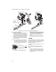
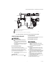
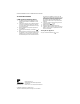
Table Of Contents

VR8204A,M INTERMITTENT PILOT COMBINATION GAS CONTROL
5 69-0423—04
Fig. 7. Wiring connections for 24 volt control in intermittent ignition system with S86.
STARTUP AND CHECKOUT
WARNING
Fire or Explosion Hazard
Can cause property damage, severe injury, or
death.
1. Do not force the gas control knob. Use only
your hand to turn the gas control knob. Never
use any tools.
2. If the gas control knob will not operate by hand,
call a qualified service technician to replace
the gas control.
Gas Control Knob Settings
The gas control knob settings are as follows:
OFF prevents pilot and main gas flow through the control.
ON permits gas to flow into the control body. Under
control of the thermostat and intermittent pilot module,
gas can flow to the pilot and main burners.
NOTE: Controls are shipped with the gas control knob
in the ON position.
Turn On System
Rotate the gas control knob counterclockwise to
ON.
Turn On Main Burner
Follow instructions provided by appliance manufacturer
or turn up thermostat to call for heat.
Perform Gas Leak Test
WARNING
Fire or Explosion Hazard
Can cause property damage, severe injury, or
death.
Check for gas leaks with soap and water solution
any time work is done on a gas module.
Gas Leak Test
1. Paint pipe connections upstream of gas control
with rich If a gas leak is detected, tighten the pipe
connection.
2. If leak is detected, tighten pipe connections.
3. Stand clear of main burner while lighting to prevent
injury caused from hidden leaks which could cause
flashback in the appliance vestibule. Light main
burner.
4. With main burner in operation, pain pipe joints
(including adapters) and control inlet and outlet
with rich soap and water solution.
5. If another leak is detected, tighten adapter screws,
joints, and pipe connections.
6. Replace part if leak can’t be stopped.
2
S86 MODULE
24V
(1) (GND)
MV
GND
(BURNER)
PILOT GAS
SUPPLY
PILOT BURNER
GROUND
Q345, Q346, Q348,
Q362, Q381
PILOT BURNER/
IGNITER-SENSOR
THERMOSTAT
OR CONTROLLER
PV/MV
PV
MV
PV/MV
PV
L1
(HOT)
(HOT)
L2
1
4
POWER SUPPLY. PROVIDE DISCONNECT MEANS AND OVERLOAD PROTECTION AS REQUIRED.
ALTERNATE LIMIT CONTROLLER LOCATION.
MAXIMUM CABLE LENGTH 3 FT (0.9M).
CONTROLS IN 24V CIRCUIT MUST NOT BE IN GROUND LEG TO TRANSFORMER.
2
3
4
1
LIMIT
CONTROLLER
AIR PROVING
SWITCH
COMBUSTION
AIR BLOWER
MOTOR
L2
L1
3
M18851
24V (2)
GAS CONTROL
TERMINALS
COMBUSTION
AIR BLOWER
RELAY