
Install Instructions


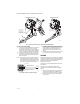
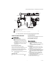
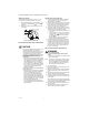
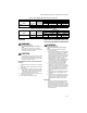
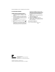
Table Of Contents

VR8204A,M INTERMITTENT PILOT COMBINATION GAS CONTROL
3 69-0423—04
Install Piping to Gas Control
All piping must comply with local codes and ordinances
or with the National Fuel Gas Code (ANSI Z223.1 NFPA
No. 54), whichever applies. Tubing installation must
comply with approved standards and practices.
1. Use new, properly reamed pipe free from chips. If
tubing is used, make sure the ends are square,
deburred and clean. All tubing bends must be
smooth and without deformation.
2. Run pipe or tubing to the control. If tubing is used,
obtain a tube-to-pipe coupling to connect the tub-
ing to the control.
3. Install sediment trap in the supply line to the gas
control. See Fig. 2.
Install Gas Control
1. This control can be mounted 0-90 degrees, in any
direction, from the upright position of the gas con-
trol knob, including vertically.
2. Mount the control so gas flow is in the direction of
the arrow on the bottom of the control.
3. Thread pipe the amount shown in Table 2 for inser-
tion into control of adapter. DO NOT THREAD PIPE
TOO FAR. Valve distortion or malfunction may
result if the pipe is inserted too deeply.
Fig. 2. Install sediment trap.
4. Apply a moderate amount of good quality pipe
compound (do not use Teflon tape) to pipe only,
leaving two end threads bare. On LP installations,
use compound resistant to LP gas. Refer to Fig. 3.
Fig. 3. Use moderate amount of pipe compound.
5. Remove seals over gas control inlet and outlet if
necessary.
6. Connect pipe to gas control inlet and outlet. Use
wrench on the square ends of the gas control. If a
flange is used, place wrench on flange rather than
on gas control. Refer to Fig. 4 and 5.
Fig. 4. Top view of gas control.
GAS
CONTROL
GAS
CONTROL
HORIZONTAL
DROP
PIPED
GAS
SUPPLY
PIPED
GAS
SUPPLY
3 IN.
(76 MM)
MINIMUM
3 IN.
(76 MM)
MINIMUM
RISER
GAS
CONTROL
TUBING
GAS
SUPPLY
HORIZONTAL
DROP
3 IN.
(76 MM)
MINIMUM
RISER
M3077C
2
1
2
2
1
2
ALL BENDS IN METALLIC TUBING SHOULD BE SMOOTH.
CAUTION: SHUT OFF THE MAIN GAS SUPPLY BEFORE REMOVING
END CAP TO PREVENT GAS FROM FILLING THE WORK AREA. TEST
FOR GAS LEAKAGE WHEN INSTALLATION IS COMPLETE.
Table 2. NPT pipe thread length in (in.).
Pipe Size
Thread Pipe
this Amount
Maximum Depth Pipe can
be Inserted into Control
3/8 9/16 3/8
1/2 3/4 1/2
3/4 13/16 3/4
TWO IMPERFECT
THREADS
GAS CONTROL
THREAD PIPE THE AMOUNT
SHOWN IN TABLE FOR
INSERTION INTO GAS CONTROL
APPLY A MODERATE AMOUNT OF
PIPE COMPOUND TO PIPE ONLY
(LEAVE TWO END THREADS BARE).
M3075D
PIPE