
NG to LP Conversion Guide
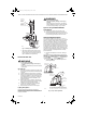

Table Of Contents

396021 LP GAS AND 396025 NATURAL GAS CONVERSION KITS FOR VR8200/VR8300/SV9400/SV9500/SV9600
69-1238—2 2
Fig. 1. Installing the conversion kit.
c. ON: Permits gas to flow through the control
body to the main burner under control of the
ignition system (and controls the pilot burner
gas in intermittent pilot applications).
Perform Gas Leak Test
WARNING
Fire or Explosion Hazard.
Can cause property damage, severe injury
or death.
Perform Gas Leak Test every time work is done on
a gas system.
Gas Leak Test
1. Paint pipe connections upstream of the gas control
with rich soap and water solution. Bubbles indicate
a gas leak.
2. If a leak is detected, tighten the pipe connections.
3. Light the pilot burner and main burner as described
in Lighting the Appliance. Stand clear of the main
burner while lighting to prevent injury caused from
hidden leaks that could cause flashback in the
appliance vestibule.
4. With the main burner in operation, paint the pipe
joints (including adapters) and the control inlet and
outlet with a rich soap and water solution.
5. If another leak is detected, tighten the adapter
screws, joints, and pipe connections.
6. Replace the part if a leak cannot be stopped.
Lighting the Appliance
Follow the appliance manufacturer instructions, if
available, for lighting the pilot burner and main burner. If
the manufacturer instructions are not available, use the
following information.
WARNING
Fire or Explosion Hazard.
Can cause property damage, severe injury,
or death.
Stand away from the main burner while lighting,
because flashbacks caused by hidden gas leaks
can cause property damage, injury or death.
Appliances Using SV9400/SV9500/SV9600
Ignition Modules
1. Set the ignition system control switch to ON.
2. Follow the appliance manufacturer instructions or
adjust the thermostat setting to call for heat. Do not
try to manually light the pilot or the main burner.
Check and Adjust Pilot Flame
The pilot flame should envelop 3/8 to 1/2 in. (10 to 13
mm) of the tip of the thermocouple or flame rod. It should
also be in continual contact with the ground electrode if
this is an IP application. See Fig. 2. If the pilot flame is
small or lazy, or does not touch the ground electrode or
thermocouple, the inlet gas pressure may be too low, or
the pilot orifice may be partially clogged. Check and repair
as necessary. If the pilot flame is hard and noisy, the inlet
gas pressure may be too high. The IP and standing pilot
controls have a pilot adjustment mechanism to reduce the
pilot flow if necessary. If pilot adjustment is necessary,
proceed as follows:
1. Remove pilot adjustment cover screw. See Fig. 3
and 4.
The pilot adjustment is shipped at the full pilot gas flow
rate. Using a screwdriver, turn the inner adjustment screw
clockwise if the inlet pressure is too high. Turn the
inner adjustment screw clockwise to decrease or
counterclockwise to increase pilot flame.
2. Replace the cover screw after the adjustment to
prevent gas leakage.
Fig. 2. Proper flame adjustment.
M12944A
PRESSURE
REGULATOR
COVER
A
SSEMBLY
STEM/SPRING
A
SSEMBLY
(BLACK—LP GAS;
WHITE—NATURAL GAS)
PROPER FLAME
ADJUSTMENT
3/8 TO 1/2 IN.
(10 TO 13 MM)
THERMOCOUPLE
PROPER FLAME
ADJUSTMENT
HOT SURFACE
IGNITER
FLAME ROD
M12998
GROUND
ELECTRODE
3/8 TO 1/2 IN.
(10 TO 13 MM)
NOTE: GROUND ELECTRODE MUST NOT TOUCH FLAME
ROD (.050 IN. MINIMUM CLEARANCE). BEND GROUND
ELECTRODE IF NECESSARY. DO NOT BEND FLAME ROD.
69-1238-2.fm Page 2 Tuesday, January 25, 2005 8:29 AM