
Install Instructions


V8200A,C,H,M AND VR8200A,C,H,M CONTINUOUS PILOT COMBINATION GAS CONTROLS
5 69-0422—05
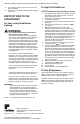
All wiring must comply with applicable electrical codes
and ordinances.
Disconnect power supply before making wiring
connections to prevent electrical shock or equipment
damage.
1. Check the power supply rating on the valve and
make sure it matches the available supply. Install
transformer, thermostat and other controls as
required.
2. Connect control circuit to gas control terminals.
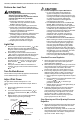
Refer to Fig. 4 and 8.
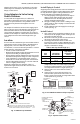
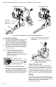
Connect Supplementary Limit or ECO (if
used)
The leadwires from the high limit or ECO must be
equipped with insulated 1/4 in. female quick-connect
terminals. Leadwire lengths must not exceed the lengths
shown in Tables 5 and 6. Connect the high-limit or ECO
leadwires to the two terminals on the ECO connector.
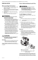
Fig. 8. Wiring Connections.
Table 5. Maximum Length of Supplementary Limit
Leadwires when using Q340A Thermocouple.
Table 6. Maximum Length of Supplementary Limit Lead-
wires when using Q309A Thermocouple.
STARTUP AND CHECKOUT
WARNING
Fire or Explosion Hazard can cause property
damage, severe injury or death.
Do not force the gas control knob on the
appliance. Use only your hand to push down the
reset button or turn the gas control knob. Never
use any tools.
If the knob or reset button will not operate by
hand, or if the reset button stays depressed after
it is released, the control should be replaced by a
qualified service technician.
Gas Control Knob Settings
Gas Control knob settings are as follows:
OFF prevents pilot and main gas flow through the control.
PILOT permits gas to flow to the pilot burner as long as
red knob is held down or thermocouple current is above
the power unit dropout value.
ON permits gas to flow into the control body. Pilot gas is
controlled as in the PILOT position. Main burner gas flow
is controlled by the thermostat and automatic valve
operator(s).
NOTE: Valves are shipped with the gas control knob in
the ON position.
Thermocouple
Length
Maximum Leadwires Length X 2
(wires)
AWG
No. 14
AWG
No. 16
AWG
No. 18
Inches Meters in. m in. m in. m
12 0.3 41 1.0 26 0.7 16 0.4
18 0.5 35 0.9 22 0.6 13 0.3
24 0.6 29 0.7 18 0.5 11 0.3
30 0.8 23 0.6 15 0.4 9 0.2
36 0.9 17 0.4 11 0.3 6 0.2
40 1.0 130.380.2
48 1.2
DO NOT USE
54 1.4
60 1.5
72 1.8
L1
(HOT)
L2
1
24V
THERMOSTAT
OPTIONAL
CONVENIENCE
TERMINALS
TH/TR
TH
TR
GAS CONTROL
TERMINALS
HIGH LIMIT
CONTROLLER
POWER SUPPLY. PROVIDE DISCONNECT MEANS AND OVERLOAD
PROTECTION AS REQUIRED.
DO NOT JUMPER THESE TERMINALS. THIS SHORTS VALVE COIL
AND CAN BURN OUT ANTICIPATOR IN THERMOSTAT.
CONVENIENCE TERMINALS SERVE ONLY AS A TIE POINT.
THEY ARE NOT INTERNALLY WIRED TO THE CONTROL CIRCUIT
OR TO GROUND.
OPTIONAL HIGH LIMIT.
1
2
3
4
2
3
4
M2915A
Thermocouple
Length
Maximum Leadwires Length X 2
(wires)
AWG
No. 14
AWG
No. 16
AWG
No. 18
Inches Meters in. m in. m in. m
12 0.3 47 1.2 30 0.8 18 0.5
18 0.5 41 1.0 26 0.7 16 0.4
24 0.6 35 0.9 22 0.6 14 0.4
30 0.8 29 0.8 18 0.5 11 0.3
36 0.9 23 0.6 15 0.4 9 0.2
40 1.0 19 0.5 12 0.3 7 0.2
48 1.2 11 0.3 7 0.2
54 1.4
DO NOT USE60 1.5
72 1.8