
Install Instructions

V8200A,C,H,M AND VR8200A,C,H,M CONTINUOUS PILOT COMBINATION GAS CONTROLS
7 69-0422—05
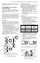
3. If necessary, adjust pressure regulator to match
appliance rating. Refer to Table 7 for factory set
nominal outlet pressure and adjustment range.
a. Remove pressure regulator adjustment cap
screw.
b. Using screwdriver, turn inner adjustment screw
clockwise to increase or counterclock-
wise to decrease gas pressure to burner
c. Always replace cap screw and tighten firmly to
ensure proper operation.
4. If desired outlet pressure or flow rate cannot be
achieved by adjusting the control, check the inlet
pressure using a manometer at inlet pressure tap
or upstream of the gas control. If inlet pressure is
in the normal range (refer to Table 7), replace the
existing control. Otherwise, take the necessary
steps to provide proper gas pressure to the control.
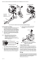
5. STEP-OPENING PRESSURE REGULATORS ONLY.
Carefully check burner lightoff at step pressure.
Make sure burner lights smoothly and without
flashback to orifice. Make sure all ports remain lit.
Cycle burner several times, allowing at least 30
seconds between cycles for regulator to resume
step function. Repeat after allowing burner to cool.
Readjust full rate outlet pressure if necessary to
improve lightoff characteristics.
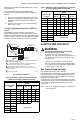
Table 7. Pressure Regulator Specification Pressures in
in. wc.
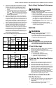
Table 8. Pressure Regulator Specification Pressures in
kPa.
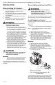
Check Safety Shutdown Performance
WARNING
Fire or Explosion Hazard can cause property
damage, severe injury or death.
Perform the safety shutdown test any time work
is done on a gas system.
1.
Place gas control knob in PILOT position. Main
burner should go off and pilot should remain lit.
2. Extinguish pilot flame. Pilot gas flow should
stop within 2-1/2 minutes. Safety shutoff of
pilot gas proves complete shutdown since
safety shutoff valve blocks flow of gas to main
burner and pilot.
3. Relight pilot burner and operate system
through one complete cycle to make sure all
controls operate properly.
SERVICE
WARNING
Fire or Explosion Hazard can cause property
damage, severe injury or death.
Do not take this control apart; it contains no
replaceable components. Attempted disassembly
or repair may damage the control.
CAUTION
Do not apply jumper across (or short) the valve
coil terminals, even temporarily. Doing so may
burn out the heat anticipator in the thermostat.
If Pilot Will Not light
1. Make sure the main gas supply valve is open and
the pilot gas supply line is purged of air.
2. Attempt to light pilot following procedure in “Light
Pilot” on page 6.
3. If pilot will not light, check for:
a. closed pilot gas adjustment screw.
b. clogged pilot burner tubing or orifice.
c. gas leak at compression fitting.
If Pilot Goes Out When Reset Button
Is Released
1. Make sure the reset button is held in at least one
minute to allow the thermocouple time to heat.
2. Check pilot flame adjustment, see page 6.
3. Check the connection to the power unit. This is an
electrical connection and must be clean and secure.
4.
If pilot still goes out, use a millivoltmeter to measure
the exact open circuit output voltages of the
thermocouple. Compare to acceptable range charts
in the thermocouple specifications. Replace the
thermocouple if voltages are outside the acceptable
range; otherwise, replace the gas control.
If Main Burner Will Not Come On
With Call For Heat
1. Confirm that gas control knob is in the ON position.
2. Adjust thermostat several degrees above room
temperature
3. Using ac voltmeter, measure voltage across
thermostat terminals at gas control.
Model
Type
Type
of
Gas
Nominal
Inlet
Pressure
Range
Factory Set
Nominal
Outlet
Pressure
Setting
Range
Step
Full
Rate Step
Full
Rate
Standard,
Slow
NAT 5.0 - 7.0 - 3.5 - 3 - 5
LP
12.0 - 14.0
- 10.0 - 8 - 12
Step NAT 5.0 - 7.0 0.9 3.5 None 3 - 5
LP
12.0 - 14.0
2.2 10.0 None 8 - 12
Model
Type
Type
of
Gas
Nominal
Inlet
Pressure
Range
Factory Set
Nominal
Outlet
Pressure
Setting
Range
Step
Full
Rate Step
Full
Rate
Standard,
Slow
NAT 1.2 - 1.7 - 0.9 - 0.7 - 1.2
LP 2.9 - 3.9 - 2.5 - 2 - 3
Step NAT 1.2 - 1.7 0.2 0.9 None 0.7 - 1.2
LP 2.9 - 3.9 0.5 2.5 None 2 - 3