
NG to LP Conversion Guide
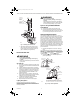
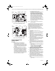
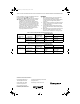
Table Of Contents

396021 LP GAS AND 396025 NATURAL GAS CONVERSION KITS FOR VR8200/VR8300/SV9400/SV9500/SV9600
3 69-1238—2
Fig. 3. Top view of VR8204 Gas Control.
Fig. 4. Top view of SV9500 Gas Control.
Check and Adjust Gas Input
and Burner Ignition
IMPORTANT
1. Do not exceed input rating stamped on
appliance nameplate, or manufacturer
recommended burner orifice pressure for size
orifice(s) used. Make certain primary air supply
to main burner is properly adjusted for complete
combustion. Follow appliance manufacturer
instructions.
2. IF CHECKING GAS INPUT BY CLOCKING
GAS METER: Make certain there is no gas flow
through the meter other than to the appliance
being checked. Other appliances must remain
off with the pilots extinguished (or deduct the
consumption from the meter reading). Convert
flow rate to Btuh as described in form 70-2602,
Gas Controls Handbook, and compare to Btuh
input rating on appliance nameplate.
3. IF CHECKING GAS INPUT WITH
MANOMETER: Make sure the gas control knob
or the ignition control switch is in the OFF
position before removing outlet pressure tap
plug to connect manometer (pressure gauge).
Also move the gas control knob or the ignition
system control switch to the OFF position when
removing the gauge and replacing the plug.
Before removing the inlet pressure tap plug,
shut off the gas supply at the manual valve in
the gas piping to the appliance or, for LP, at the
tank. Also shut off the gas supply before
disconnecting the manometer and replacing the
plug. Repeat the Gas Leak Test at the plug with
the main burner operating.
NOTE: Check the inlet pressure before adjusting the
pressure regulator.
Two-stage regulator models require that you check and
adjust both high and low pressure regulator settings.
Two-stage appliance operating sequences vary, consult
the appliance manufacturer instructions for the specific
operating sequence and regulator adjustment
procedures for the appliance in which the control is
installed. The regulator adjustment instruction for a
two-stage Honeywell SmartValve™ System Control is as
follows:
1. Set thermostat 10 degrees above room
temperature.
2. Carefully check the main burner lightoff. Make sure
that the main burner lights smoothly and that all
ports remain lit.
3. Wait for control to move to high pressure (second
stage) and then check the full rate manifold
pressure listed on the appliance nameplate for high
pressure. The gas control full rate outlet pressure
should match this rating.
4. With main burner operating, check the gas control
flow rate using the meter clocking method or check
pressure using a manometer connected to the
outlet pressure tap on the control.
See Fig. 3 and 4.
5. If necessary, adjust the high pressure regulator to
match the appliance rating. See Tables 1 and 2 for
factory-set nominal outlet pressure and adjustment
range.
a. Remove the pressure regulator adjustment cap
(Fig. 3 and 4).
b. Using a screwdriver, turn the inner adjustment
screw for HI pressure clockwise to
increase or counterclockwise to
decrease the gas pressure to the burner.
6. After high pressure is checked, check low pressure
regulation by removing the wire from terminal W2
of the ST9162 Fan Timer (to prevent ignition
control from moving to high stage).
7. Check the low rate manifold pressure listed on the
appliance nameplate. Gas control low rate outlet
pressure should match this rating.
8. With main burner operating, check the control flow
rate as before (using the meter clocking method or
check pressure using a manometer connected to
the outlet pressure tap on the control).
9. If necessary, adjust the low pressure regulator to
match the appliance rating. See Tables1and 2 for
factory-set nominal outlet pressure and adjustment
range.
a. Remove the pressure regulator adjustment cap
(Fig. 3 and 4).
M12999
REGULATOR
VENT COVER
INLET
PRESSURE TAP
HI
LO
WIRING
TERMINALS
(3)
CONVENIENCE
TERMINALS (2)
(OPTIONAL)
PILOT ADJUSTMENT
(UNDER CAP SCREW)
GAS
CONTROL
KNOB
RED
RESET BUTTON
PILOT
OUTLET
THERMOCOUPLE
CONNECTION
OUTLET
PRESSURE
TAP
HI-LO
ADJUSTMENT
SCREWS
(UNDER CAP)
OFF
ON
C1
C2
C3
HI
LO
M12948
HI-LO
A
DJUSTMENT
SCREWS
(UNDER CAP)
REGULATOR
VENT COVER
INLET
PRESSURE TAP
IGNITION SYSTEM
CONTROL SWITCH
CONTROLS
CONNECTOR
PILOT
OUTLET
OUTLET
PRESSURE TAP
IGNITER
CONNECTOR
LINE VOLTAGE
CONNECTOR
69-1238-2.fm Page 3 Tuesday, January 25, 2005 8:29 AM