
Wiring Guide
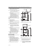
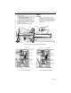
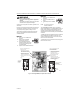
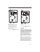
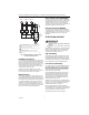
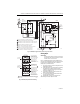
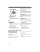
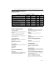
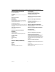
Table Of Contents
- Application
- Installation
- Wiring
- Operation
- Startup and Checkout
- Material Safety Data Sheet (MSDS)
- Section 1. Product and Company Identification.
- Section 2. Composition, Information on Ingredients (Table 1).
- Section 3. Hazard Identification
- Section 4. First Aid Measures
- Section 5. Fire Fighting Measures
- Section 6. Accidental Release Measures
- Section 7. Handling and Storage
- Section 8. Exposure Controls and Personal Protection
- Section 9. Physical and Chemical Properties
- Section 10. Stability and Reactivity
- Section 11. Toxicology Information
- Section 12. Ecological Information
- Section 13. Disposal Consideration
- Section 14. Transportation Information
- Section 15. Regulatory Information
- Section 16. Other Information

R8182D,H COMBINATION PROTECTORELAY™ PRIMARY CONTROL AND AQUASTAT
®
CONTROLLER
7 69-0599—2
Fig. 10. R8182D,H in typical zone system using zone valves.
Fig. 11. R8182D,H Aquastat limit switching.
Setting Stops
IMPORTANT
Once the setting stops are in place, they cannot
be replaced. If they must be removed, cut them
off with cutters—do not twist off.
Part no. 126580 Setting Stops can be installed on the
low- and high-limit adjusting knobs to prevent turning the
knobs beyond a predetermined point. To install the
setting stops, proceed as follows:
1. On low-limit knob, turn knob to setting that is to be
established as the limit.
2. Place setting stop over knob so that arm of setting
stop (after stop is pressed into place) strikes
projection A and prevents turning of knob beyond
chosen limit setting (Fig. 11).
3. Press setting stop tightly onto knob so its inner
teeth securely engage knob.
4. Turn knob back and forth several times to make
sure stop functions properly.
5. Repeat steps 1 through 4 for high-limit knob.
After settings are made, replace the cover.
M4521
L1
(HOT)
L2
1
5
4
6
3
2
1
2
4
3
6
5
120 VAC POWER SUPPLY. PROVIDE DISCONNECT
MEANS AND OVERLOAD PROTECTION AS REQUIRED.
THERMOSTAT HEAT ANTICIPATOR SETTING, 0.2 AMP FOR R8182D.
THERMOSTAT HEAT ANTICIPATOR SETTING, 0.4 AMP FOR R845A.
CONTROL CASE MUST BE CONNECTED TO EARTH
GROUND. USE GROUNDING SCREW PROVIDED.
R8182E,H,J CONNECTIONS FROM ZC AND ZR ARE IDENTICAL
FOR MULTIPLE CIRULATOR ZONING APPLICAITON.
EACH ADDITIONAL ZONE REQUIRES A SEPARATE,
FIELD-ADDED 24V THERMOSTAT AND R845 RELAY.
24 VOLT
THERMOSTAT
B2
C2
C1
ZR
ZC
B1R
B
HIGH LIMIT
1K1
1K2
2K1
1K
1K1
1K2
B
R
W
LOW
LIMIT
1K
2
1
G
T T F F
R8182D
2K
2K2
BILATERAL
SWITCH
CIRCULATOR
C554A
R2
C1
S.SW
CONTACTS
SAFETY
SWITCH
HEATER
TRIAC
R1
TO WATER
CIRCULATOR
TO OIL
BURNER
AND
IGNITION
BLUE
2
1
T
T
5 3
6 4
ZONE 2
THERMOSTAT
R845A
SWITCHING
RELAY ZONE 2
ZONE 2
CIRCULATOR
TO ADDITIONAL
ZONES 3, 4, ETC.
LOW LIMIT
AND
CIRCULATOR
SETTING
HIGH LIMIT
SETTING
SWITCH BREAKS ON
TEMPERATURE RISE.
BURNER TURNS OFF.
CIRCULATOR OPERATES
ON A CALL FOR HEAT.
SWITCH MAKES ON
TEMPERATURE FALL.
BURNER OPERATES ON A
CALL FOR HEAT.
SWITCH MAKES R-W
AND BREAKS R-B ON
TEMPERATURE RISE.
SWITCH MAKES R-B AND
BREAKS R-W ON
TEMPERATURE FALL.
BURNER IS ON TO
MAINTAIN MINIMUM
WATER TEMPERATURE.
CIRCULATOR IS OFF.
M1523
SWITCH MAKES R-W
AND BREAKS R-B ON
TEMPERATURE RISE.
WHEN WATER REACHES PROPER TEMPERATURE, THE BURNER
SHUTS OFF OR THE CIRCULATOR PUMP STARTS (WHEN CALLING
FOR HEAT).
1
1