
Wiring Guide
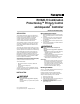
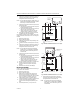
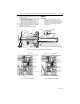
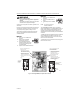
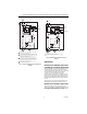
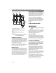
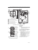
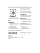
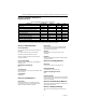
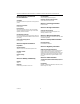
Table Of Contents
- Application
- Installation
- Wiring
- Operation
- Startup and Checkout
- Material Safety Data Sheet (MSDS)
- Section 1. Product and Company Identification.
- Section 2. Composition, Information on Ingredients (Table 1).
- Section 3. Hazard Identification
- Section 4. First Aid Measures
- Section 5. Fire Fighting Measures
- Section 6. Accidental Release Measures
- Section 7. Handling and Storage
- Section 8. Exposure Controls and Personal Protection
- Section 9. Physical and Chemical Properties
- Section 10. Stability and Reactivity
- Section 11. Toxicology Information
- Section 12. Ecological Information
- Section 13. Disposal Consideration
- Section 14. Transportation Information
- Section 15. Regulatory Information
- Section 16. Other Information

R8182D,H COMBINATION PROTECTORELAY™ PRIMARY CONTROL AND AQUASTAT
®
CONTROLLER
69-0599—2 6
Fig. 9. R8182D and R845A in typical multiple
circulator zoning application.
R8182D,H (triple-function)
A call for heat by the thermostat pulls in 1K and 2K relays
to turn on the burner, and the safety switch starts to heat.
If the burner ignites within 45 seconds, the cad cell sees
the flame and the safety switch heater is bypassed. The
burner operates until the call for heat is satisfied. The
circulator operates when relay 1K pulls in only if R to W
in the Aquastat¨ controller is made.
When R to B (low limit) is made by a drop in water
temperature, it acts as a call for heat, pulling in relay 2K
to turn on the burner. Circulator cannot operate.
Multizone Control
In all multizone applications, a call for heat in any zone
energizes the safety switch circuit and relay 2K pulls in. If
burner ignites within the safety switch timing, the cad cell
sees the flame and the safety switch heater is bypassed.
In all multizone applications, the low-limit control in the
Aquastat¨ controller acts independently to turn on the
main burner on a drop in water temperature. When R to
B (low- limit) is made, relay 2K pulls in to turn on the main
burner, the same as for single zone applications.
Zone Circulator Control with R8182D,H
The relay for each zone is connected to the Aquastat
Controller through terminals ZC and ZR. The R845 relay
and thermostat for each zone can energize the zone
circulator through ZC only if R to W in the Aquastat
controller is made. If R to B (high-limit) is made, the zone
thermostat energizes the burner through ZR.
Zone Valve Control with R8182D,H
The valve for each zone is connected to the Aquastat
controller by wiring end switches on the zone valve to T-T
on the R8182D,H. On a call for heat from any zone, the
R8182D,H operates the same as in a single zone
application.
STARTUP AND CHECKOUT
WARNING
Explosion Hazard.
Can cause severe injury, death or equipment
damage.
Use this product only in systems with a pressure relief
valve.
Because heating systems differ, the correct temperature
setting for one system may not be correct for another.
Follow the boiler manufacture recommendations for
proper selection of settings. See Fig. 11
.
High-Limit Setting
The high-limit opens and turns off the burner when the
water temperature reaches the setpoint. The high-limit
automatically resets after the water temperature drops
past the setpoint and through the 10°F (6°C) differential.
Set the indicator at the desired shutoff temperature.
Low-Limit /Circulator Setting
On a temperature rise, with the adjustable differential at
the minimum setting of 10°F (6°C), the burner circuit
(R-B) breaks and the circulator circuit (R-W) makes at
the low- limit setpoint. See Fig. 11. On a temperature
drop of 10°F (6°C) below the setpoint, the R-B circuit
makes and the R-W circuit breaks.
At any differential setting greater than 10°F (6°C), the
R-B make temperature and R-W break temperature
remains the same—control setting minus 10°F (6°C).
The R-B break and R-W make temperature are the
setpoint temperature plus the difference between the
differential setting and 10°F (6°C).
EXAMPLE: Setpoint of 140°F (60°C), differential set at
25°F (14°C). On a temperature rise, R-B breaks and R-W
makes at 155°F (70°C). On a temperature fall, R-B
makes and R-W breaks at 130°F (54°C).
Set low-limit indicator at the minimum temperature
recommended for domestic hot water supply. This setting
must be at least 20°F (11°C) below high-limit setting to
prevent one switch from locking out the other.
Set differential the desired number of degrees.
L1
(HOT)
L2
1
1
2
3
4
5
5 5 5
333
4
2
POWER SUPPLY. PROVIDE DISCONNECT MEANS AND OVERLOAD
PROTECTION AS REQUIRED.
R8182H AND J HAVE WHITE AND ORANGE LEADWIRES FOR OIL
BURNER AND IGNITION CONNECTIONS.
RED LEADWIRES PROVIDED ONLY ON MODLES WITH END SWITCH.
CHOOSE AT72, AT87, OR AT88 TRANSFORMER TO MATCH
MAXIMUM SYSTEM LOAD.
USE V8043 OR V8044 ZONE VALVES WITH AUXILIARY END
SWITCH ONLY.
L1 L2
T
T
B1
B2
C1
C2
CIRCULATOR
RED
RED
RED
RED
RED
RED
YELLOW
YELLOW
YELLOW
YELLOW
YELLOW
YELLOW
24 VOLT
THERMOSTAT
24 VOLT
THERMOSTAT
24 VOLT
THERMOSTAT
TO OIL
BURNER
AND
IGNITION
M4522