
Wiring Guide
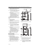
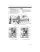
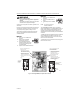
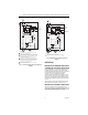
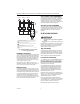
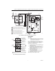
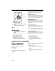
Table Of Contents
- Application
- Installation
- Wiring
- Operation
- Startup and Checkout
- Material Safety Data Sheet (MSDS)
- Section 1. Product and Company Identification.
- Section 2. Composition, Information on Ingredients (Table 1).
- Section 3. Hazard Identification
- Section 4. First Aid Measures
- Section 5. Fire Fighting Measures
- Section 6. Accidental Release Measures
- Section 7. Handling and Storage
- Section 8. Exposure Controls and Personal Protection
- Section 9. Physical and Chemical Properties
- Section 10. Stability and Reactivity
- Section 11. Toxicology Information
- Section 12. Ecological Information
- Section 13. Disposal Consideration
- Section 14. Transportation Information
- Section 15. Regulatory Information
- Section 16. Other Information

R8182D,H COMBINATION PROTECTORELAY™ PRIMARY CONTROL AND AQUASTAT
®
CONTROLLER
3 69-0599—2
8. If necessary, apply heat-conductive compound into
the immersion well.
a. Fold plastic bag of heat-conductive compound
lengthwise and twist it gently.
b. Cut off end of plastic bag and work open end of
bag all the way into the immersion well.
c. Slowly pull bag out of the immersion well while
squeezing it firmly to distribute compound.
9. Tighten the immersion well screw over brass collar.
10. After wiring, swing control case against backplate
and refasten it with screw.
11. Refill the boiler and check for water leakage.
WIRING
IMPORTANT
• Use Underwriters Laboratories Inc. listed
connectors when making external circuit
connections to the orange and white line votage
burner and ignition leadwires of the R8182H.
• Terminals on the R8182 are approved for
copper wire only.
Fig. 3. Positioning the sensing bulb in the immersion well.
Fig. 4. Internal view of R8182D.
Fig. 5. Internal view of R8182H.
CONTROLLER
CASE
IMMERSION
WELL CLAMP
ADAPTER
IMMERSION
WELL SPUD
BOILER
OLD IMMERSION
WELL ASSEMBLY
BACK OF
CONTROLLER
CASE
IMMERSION
WELL CLAMP
SCREW
ADAPTER
SENSING
BULB
HEAT-CONDUCTIVE COMPOUND
SETSCREW
CAPILLARY
TUBE
(C)
IMMERSION
WELL CLAMP
IMMERSION
WELL CLAMP SCREW
SHORT TUBE
FITS IN CENTRAL
RECESS OF ADAPTER
BEND THE CAPILLARY TUBE TO HOLD THE SENSING BULB IN GOOD
THERMAL CONTACT WITH THE IMMERSION WELL AT POINTS (A) AND (B).
ASSURE THAT CAPILLARY TUBE FITS FREELY IN THE ADAPTER SO THE
TENSION OF THE CAPILLARY TUBE AT POINT (C) HOLDS THE SENSING
BULB IN GOOD THERMAL CONTACT WITH THE IMMERSION WELL AT POINT (D).
M8830
1
1
2
2
(D)
(B)
(A)
M4524
SAFETY SWITCH
RESET BUTTON
DIFFERENTIAL
SETTING
CIRCULATOR
RELAY (1K)
LOW LIMIT
SETTING
HIGH LIMIT
SETTING
VOLTAGE BARRIER
BURNER MOTOR
AND IGNITION
RELAY (2K)
TRANSFORMER
FOR THERMOSTAT
CIRCUIT
TRANSFORMER FOR
CAD CELL CIRCUIT
CAD CELL
LEADS (YELLOW)
M4525
SAFETY SWITCH
RESET BUTTON
DIFFERENTIAL
SETTING
CIRCULATOR
RELAY (1K)
LOW LIMIT
SETTING
HIGH LIMIT
SETTING
VOLTAGE BARRIER
BURNER MOTOR
AND IGNITION
RELAY (2K)
GROUNDING SCREW
TRANSFORMER
FOR THERMOSTAT
CIRCUIT
TRANSFORMER FOR
CAD CELL CIRCUIT