
Wiring Guide
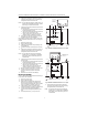
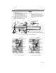
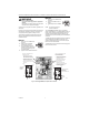
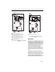
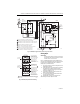
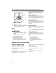
Table Of Contents
- Application
- Installation
- Wiring
- Operation
- Startup and Checkout
- Material Safety Data Sheet (MSDS)
- Section 1. Product and Company Identification.
- Section 2. Composition, Information on Ingredients (Table 1).
- Section 3. Hazard Identification
- Section 4. First Aid Measures
- Section 5. Fire Fighting Measures
- Section 6. Accidental Release Measures
- Section 7. Handling and Storage
- Section 8. Exposure Controls and Personal Protection
- Section 9. Physical and Chemical Properties
- Section 10. Stability and Reactivity
- Section 11. Toxicology Information
- Section 12. Ecological Information
- Section 13. Disposal Consideration
- Section 14. Transportation Information
- Section 15. Regulatory Information
- Section 16. Other Information

® U.S. Registered Trademark
Copyright © 2002 Honeywell • All Rights Reserved
INSTALLATION INSTRUCTIONS
69-0599-2
R8182D,H Combination
Protectorelay™ Primary Control
and Aquastat
®
Controller
APPLICATION
The R8182D,H Controllers combine a Protectorelay™
Primary Control and an Aquastat® Controller for use in
oil-fired, hydronic heating systems. The Aquastat
Controller provides high and low limit protection,
circulator control, and minimum water temperature
control for tankless domestic hot water service.
The Protectorelay Primary Control provides control of a
line voltage, intermittent ignition oil burner when used
with a C554A Cadmium Sulfide Flame Detector and a
24V thermostat.
The auxiliary ZC and ZR terminals provide zone control
through an R845A Switching Relay. Each additional zone
requires a separate 24V thermostat and an R845A Relay.
The R8182D,H also provide zone control using zone
valves. Each additional zone requires a separate 24V
thermostat and a V8043 or V8044 Zone Valve. The
R8182D,H can be converted to provide only the high-limit
to replace an R8182B,E or only the limit and circulator
function to replace of the R8182C,F.
The R8182D mounts directly on the boiler. The R8182H
mounts on a 4 by 4 in. junction box and has a 5 ft. (1.5m)
capillary that allows a remote sensor location.
The R8182D includes
• Bag of heat-conductive compound for better heat
transfer.
• High- and low-limit setting stops.
• One wire nut.
To order an immersion well or a well adapter, see form
68-0440, Wells and Fittings for Temperature Controllers,
for part numbers and descriptions.
INSTALLATION
WARNING
Explosion Hazard.
Can cause severe injury, death or property
damage.
Use this product only in systems with a pressure
relief valve.
When Installing this Product…
1. Read these instructions carefully. Failure to follow
them could damage product or cause a hazardous
condition.
2. Check the ratings given in these instructions and
on the product to be sure product is suitable for
your application.
3. Be sure the installer is a trained, experienced ser-
vice technician.
4. After completing installation, use these instructions
to check product operation.
WARNING
Electrical Shock Hazard and Explosion
Hazard.
Can cause severe injury, death or equipment
damage.
1. Disconnect the power supply before beginning
installation to prevent electrical shock or
equipment damage.
2. Be sure that combustion chamber is clear of oil
or oil vapor before starting burner.
3. Be sure that the ambient temperature at the
element does not exceed 250°F (121°C).
IMPORTANT
Be sure that the sensing bulb fits snugly inside
the immersion well and that the sensing bulb
rests against the bottom of the immersion well.
If the sensing bulb does not fit snugly inside the
immersion well, use the heat-conductive
compound as described below. See Fig. 3.
Mounting the R8182D
See Fig. 1 for R8182D installation dimensions and Fig. 4
for an internal view of the R8182D.
If existing immersion well does not fit the R8182D
immersion well clamp, use a 124904 Immersion Well
Adapter, ordered separately from form 68-0040.
1. Disconnect power supply.
2. Drain all water from boiler.
3. Fasten R8182D immersion well clamp to flange on
immersion well adapter. See Fig. 3.
4. Place adapter on capillary tube.
5. Put adapter end into hole in controller case and
tighten clamp screw.