
Product Overview
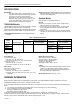
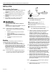
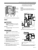
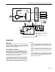
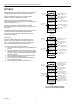
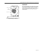
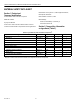
Table Of Contents
- Application
- Features
- Specifications
- Installation
- Wiring
- Operation
- Settings
- Checkout
- Material Safety Data Sheet
- Section 1. Product and Company Identification.
- Section 2. Composition, Information on Ingredients (Table 3).
- Section 3. Hazard Identification
- Section 4. First Aid Measures
- Section 5. Fire Fighting Measures
- Section 6. Accidental Release Measures
- Section 7. Handling and Storage
- Section 8. Exposure Controls and Personal Protection
- Section 9. Physical and Chemical Properties
- Section 10. Stability and Reactivity
- Section 11. Toxicology Information
- Section 12. Ecological Information
- Section 13. Disposal Consideration
- Section 14. Transportation Information
- Section 15. Regulatory Information
- Section 16. Other Information

L4081A,B AND L6081A,C MULTIPLE AQUASTAT® CONTROLLERS
60-2105—6 8
SETTINGS
Because heating systems differ, follow the boiler manufacturer
recommendations when selecting temperature settings.
Study the applicable chart in Fig. 10, which shows the
switching response to temperature changes.
With the cover off, set the high limit adjustment at the
temperature desired but not higher than recommended by the
boiler manufacturer (Fig. 4).
Set the low limit and/or circulator adjustment to obtain
temperature desired but not less than 20°F (11°C) below the
high setting.
The differential adjustment applies to only the low-limit and/or
circulator switch(es). Minimum differential adjustment
provided is 10°F (6°C) nominal; maximum is 25°F (14°C)
nominal. Set as desired.
Setting Stop
Install the 126580 Setting Stop on the adjusting knob to
prevent turning the knob beyond a predetermined point.
Fig. 11 shows stops installed on the knob of the high limit
switch to prevent setting higher than 180°F (82°C).
To install the setting stop, proceed as follows:
1. Turn the knob to the setting that is to be established as
the limit.
2. Place the setting stop over the knob in position to arm of
setting stop (after the stop is pressed into place) strikes
projection A and prevents turning the knob beyond the
desired limit setting.
3. Press the setting stop tightly onto the knob so that its
inner teeth securely engage the knob.
4. Turn knob back and forth several times to make sure
the stop functions properly.
5. When all settings are made, replace the cover.
Fig. 10. Charts showing switching
response to temperature changes.
L
OW LIMIT
S
ETTING
HIGH LIMIT
SETTING
SWITCH BREAKS ON RISE.
BURNER TURNS OFF.
SWITCH MAKES ON FALL.
BURNER OPERATES ON
A CALL FOR HEAT.
SWITCH BREAKS ON RISE.
(10°F (5.6°C) DIFFERENTIAL)
.
SWITCH MAKES ON FALL.
BURNER ON.
M8847
SWITCH BREAKS ON RISE.
(25°F (13.9°C) DIFFERENTIAL
).
10°F (5.6°C)
DIFFERENTIAL
25°F (13.9°C)
DIFFERENTIAL
10°F (5.6°C)
DIFFERENTIAL
C
IRCULATOR
S
ETTING
H
IGH LIMIT
S
ETTING
SWITCH BREAKS ON RISE.
BURNER TURNS OFF.
SWITCH MAKES ON FALL.
BURNER OPERATES ON
CALL FOR HEAT.
SWITCH MAKES ON RISE.
(10°F (5.6°C) DIFFERENTIAL).
SWITCH BREAKS ON FALL.
CIRCULATOR OFF.
110°F (43°C)
240°F (116°C)
SWITCH MAKES ON RISE.
(25°F (13.9°C) DIFFERENTIAL)
.
10°F (5.6°C)
DIFFERENTIAL
25°F (13.9°C)
DIFFERENTIAL
10°F (5.6°C)
DIFFERENTIAL
110°F (43°C)
240°F (116°C)
L4081A
L4081B
10°F (5.6°C)
DIFFERENTIAL
25°F (13.9°C)
DIFFERENTIAL
10°F (5.6°C)
DIFFERENTIAL
L
OW LIMIT AND
C
IRCULATOR
S
ETTING
H
IGH LIMIT
S
ETTING
SWITCH BREAKS ON RISE.
BURNER TURNS OFF.
CIRCULATOR OPERATES
ON CALL FOR HEAT.
SWITCH MAKES ON FALL.
BURNER OPERATES ON
CALL FOR HEAT.
SWITCH MAKES R-W AND
BREAKS R-B ON RISE.
(10°F (5.6°C) DIFFERENTIAL)
SWITCH MAKES R-B ON
FALL,BREAKS R-W ON FALL.
BURNER ON,CIRCULATOR
OFF.
110°F (43°C)
240°F (116°C)
SWITCH MAKES R-W AND
BREAKS R-B ON RISE.
25°F (13.9°C) DIFFERENTIAL.
L6081A,C