
Product Overview
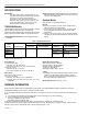
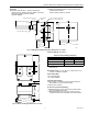
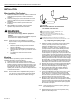
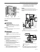
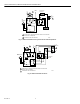
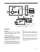
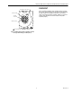
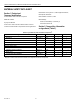
Table Of Contents
- Application
- Features
- Specifications
- Installation
- Wiring
- Operation
- Settings
- Checkout
- Material Safety Data Sheet
- Section 1. Product and Company Identification.
- Section 2. Composition, Information on Ingredients (Table 3).
- Section 3. Hazard Identification
- Section 4. First Aid Measures
- Section 5. Fire Fighting Measures
- Section 6. Accidental Release Measures
- Section 7. Handling and Storage
- Section 8. Exposure Controls and Personal Protection
- Section 9. Physical and Chemical Properties
- Section 10. Stability and Reactivity
- Section 11. Toxicology Information
- Section 12. Ecological Information
- Section 13. Disposal Consideration
- Section 14. Transportation Information
- Section 15. Regulatory Information
- Section 16. Other Information

L4081A,B AND L6081A,C MULTIPLE AQUASTAT® CONTROLLERS
60-2105—6 6
Fig. 7. L4081A used with burner cycled from the water temperature.
Fig. 8. L4081A used with oil burner.
T
T
L1
(HOT)
L2
1
2
1
2
2
4
3
1
CIRCULATOR
1R1
1R
2
4V
T
HERMO-
S
TAT
B
R
B
R
RA89A SWITCHING RELAY
L4081A
HIGH LIMIT
LOW LIMIT
M8788
POWER SUPPLY. PROVIDE DISCONNECT MEANS AND OVERLOAD
PROTECTION AS REQUIRED.
B TERMINALS ARE TAB TERMINALS.
L1
(HOT
)
L2
1
GAS VALVE
PILOTSTAT
®
CONTROL
T
T
T
T
X
X
L1
(HOT)
L2
1
2
1
2
1
2
4
3
1
CIRCULATOR
1R1
1R2
1R
2
4V
T
HERMOSTAT
B
R
B
R
RA832A SWITCHING RELAY
L4081A
HIGH LIMIT
LOW LIMIT
OIL PRIMARY
CONTROL
L2
L1
(HO
T)
JUNCTION
BOX
M8786
POWER SUPPLY. PROVIDE DISCONNECT MEANS AND OVERLOAD
PROTECTION AS REQUIRED.
B TERMINALS ARE TAB TERMINALS.
BLACK
WHITE