
Product Overview
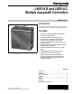
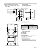
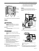
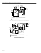
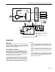
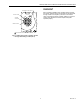
Table Of Contents
- Application
- Features
- Specifications
- Installation
- Wiring
- Operation
- Settings
- Checkout
- Material Safety Data Sheet
- Section 1. Product and Company Identification.
- Section 2. Composition, Information on Ingredients (Table 3).
- Section 3. Hazard Identification
- Section 4. First Aid Measures
- Section 5. Fire Fighting Measures
- Section 6. Accidental Release Measures
- Section 7. Handling and Storage
- Section 8. Exposure Controls and Personal Protection
- Section 9. Physical and Chemical Properties
- Section 10. Stability and Reactivity
- Section 11. Toxicology Information
- Section 12. Ecological Information
- Section 13. Disposal Consideration
- Section 14. Transportation Information
- Section 15. Regulatory Information
- Section 16. Other Information

L4081A,B AND L6081A,C MULTIPLE AQUASTAT® CONTROLLERS
60-2105—6 4
INSTALLATION
When Installing This Product…
1. Read these instructions carefully. Failure to follow them
could damage the product or cause a hazardous
condition.
2. Check the ratings given in the instructions and on the
product to make sure the product is suitable for your
application.
3. Installer must be a trained, experienced service
technician.
4. After installation is complete, check out product
operation as provided in these instructions.
WARNING
Electrical Shock Hazard.
Can cause serious injury, death or equipment
damage.
Disconnect power supply before installation to prevent
electrical shock or equipment damage.
NOTE: These devices can be installed in any position.
Proper location, sizing and threaded boiler tapping
are required.
1. Maximum pressure rating for these models is
200 psi (1380 kPa)
2. Maximum permissible ambient temperature as
sensing bulb is 265°F (130°C); at switches, 150°F
(66°C).
3. The L6081C is without enclosure or well
assembly.
Mounting
Followinstructions provided by system manufacturer, if
available. Otherwise, proceed as follows:
1. Drain the boiler if the system is filled with water.
2. Place the front of the controller down on a horizontal
surface and gently raise the sensing bulb until it is at a
right angle with the back of the case and centered with
the alrge hole in the case. This requires bending the
capillary tube, but be sure to make no sharp bends and
no bends near the bulb.
NOTE: Some models have an adjustable tubing length to
3 in. (76 mm). In these models, extra tubing inside
the case can be pulled out, if needed. See Fig. 3.
Fig. 3. Adjusting the capillary length.
3. Adjust the position of the bulb so tht the bulb projects
4-7/8 in. (124 mm) from the back of the case for
immersion well designed for 1-1/2 in. (38 mm)
insulation; or 6-3/8 in. (162 mm), if designed for 3 in.
(76 mm) insulation. If this requires bending the tube
inside the case, insert the end of your index finger
through the hole and carefully mold the tube into the
correct shape as you gently pull (or push) the bulb to the
correct position. The bulb must project the right distance
so that after the case in installed, the spring force of the
capillary tube holds the bulb against the inner end of the
well for good thermal contact. The tube must be straight
for at least 3/8 in. (10 mm) inside the case so the end of
the well spud does not strike the coiled tube and pull the
bulb away from contact with the inner end of the well.
4. Remove the plug from a properly located boiler tapping.
5. Apply pipe dope sparingly to the threads of the well,
then screw the well tightly into the boiler tapping.
6. Fill the system with water, then carefully examine
around the threads for leakage. Tighten the well if
necessary to stop any leakage.
7. Loosen the wallclamp screw three or four turns., move
the screw in and out and not how it moves the well
clamp. See Fig. 4. Loosen the screw enough so that
when the screw is pushed inward, the T-shaped clamp
guide is at the far end of the slot in the case.
8. Mount the case on the well spud in any position that
facilitates wiring. With the case in final position, carefully
insert the sensing bulb into the well until the case slips
over the end of the well spud and fits squarely against
the shoulder of the spud.
NOTE: Open the clamp to receive the spud by pushing in
the well clamp screw.
9. While holding the case in the correct position, firmly
tighten the well clamp screw.
M888
2
SENSING ELEMENT IS FACTORY FORMED FOR 1.5 IN.
INSULATION WELL ASSEMBLIES.
FOR 3 IN. INSULATION WELL ASSEMBLIES, PULL OUT
SUFFICIENT CAPILLARY TO ASSURE THAT THE CAPSULE
BOTTOMS IN THE WELL.
STRAIGHTEN CAPILLARY SUFFICIENTLY SO IT DOES NOT
INTERFERE WITH INSERTION OF THE CAPSULE INTO THE WELL.
CAUTION:
EXCESSIVE HANDLING OR SHARP BENDS
CAN DAMAGE THE CAPILLARY.
1
2
3
1
2
3