
Install Instructions
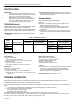
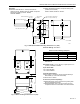
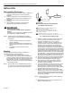
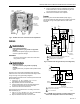
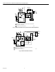
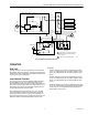
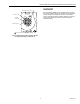
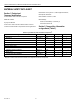
Table Of Contents
- Application
- Features
- Specifications
- Installation
- Wiring
- Operation
- Settings
- Checkout
- Material Safety Data Sheet
- Section 1. Product and Company Identification.
- Section 2. Composition, Information on Ingredients (Table 3).
- Section 3. Hazard Identification
- Section 4. First Aid Measures
- Section 5. Fire Fighting Measures
- Section 6. Accidental Release Measures
- Section 7. Handling and Storage
- Section 8. Exposure Controls and Personal Protection
- Section 9. Physical and Chemical Properties
- Section 10. Stability and Reactivity
- Section 11. Toxicology Information
- Section 12. Ecological Information
- Section 13. Disposal Consideration
- Section 14. Transportation Information
- Section 15. Regulatory Information
- Section 16. Other Information

L4081A,B AND L6081A,C MULTIPLE AQUASTAT® CONTROLLERS
5 60-2105—6
Fig. 4. L6081A with cover removed to show adjustments.
WIRING
WARNING
Electrical Shock Hazard.
Can cause serious injury, death or equipment
damage.
Disconnect the power supply to prevent electrical
shock or equipment damage.
IMPORTANT
Use care to avoid strain on the control case when
using cable or conduit.
WARNING
Explosion Hazard.
Can cause serious injury, death or property
damage.
Use this product only in a system with a pressure relief
valve.
Alll wiring must comply with all applicable local codes and
ordinances. See cover insert for electrical load ratings. Refer
to Fig. 5 through 9 for typical wiring diagrams.
Use the following procedure when connecting wires to the B-B
tab terminals (Fig. 4):
1. Connect no. 14, 16, or 18 solid, or no. 14 or 16
unistranded wire to the tab terminals.
2. Strip insulation from the end of each wire.
3. use the included wire nut from the bag assemblyh to
connect the tab terminal connector to the wire.
4. Connect the wire to the tab terminal.
Use the following procedures when connecting wires to the
R-R terminals (Fig. 4):
1. Use no. 14, 16, or 18 solid, or no. 14 or 16 unistranded
wire for connecting the push-in terminals.
2. Strip the insulation from the end of each wire.
3. Insert a screwdriver into the rectangular slot near the
terminal and hold it in the slot while inserting the wire
into the terminal hole as far as possible.
4. Remove the screwdriver when complete.
Jumper
When using the controller field addable jumper (Fig. 4),
connect terminals R-R. When the jumper is added, make sure
that the two prongs of the jumper face the center of the
controller.
Fig. 5. L4081A used with gas burner (line voltage limit).
Fig. 6. L4081B used to prevent circulator opertion with
boiler water temperature below low limit setting.
M8848
WELL CLAMP
SCREW
STRIP
GAUGE
LOW LIMIT/
CIRCULATOR
DIFFERENTIA
L
ADJUSTMENT
LOW LIMIT
SETPOINT
ADJUSTMENT
JUMPER
SLOT
HIGH LIMIT
SETPOINT
ADJUSTMENT
L1
(HOT)
L2
1
2
1
POWER SUPPLY. PROVIDE DISCONNECT MEANS AND
OVERLOAD PROTECTION AS REQUIRED.
B TERMINALS ARE TAB TERMINALS.
B
R
B
R
HIGH LIMIT
LOW LIMIT
JUMPER
REMOVED
L4081A
T
T
X
X
1R2
RA832A
SWITCHING
RELAY
2431
2
4V
T
HERMOSTAT
1R
VR8300
LOW
VOLTAGE
GAS
VALVE
CIRCULATOR
M8846
2
M8787
1
1
2
2
B
R
W
R
HIGH LIMIT
CIRCULATOR
L2
L1
(HOT)
POWER SUPPLY. PROVIDE DISCONNECT MEANS AND OVERLOAD
PROTECTION AS REQUIRED.
B IS A TAB TERMINAL.
CIRCULATOR
RELAY
BURNER
CONTROL
CIRCULATOR
MOTOR
JUMPER
REMOVED
L4081B