
Product Overview


l-
W-y
141 3, ,794,
t-’
,\ 16 IN ,116 6, ON L4066G.
A
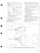
2 AYAILABLE AS OPTIONS-_).5/6 IN p2.1 mm, OR 5 IN ,127.o mm,.
FIG. 2-L4080D,G INSTALLATION DIMENSIONS IN in. [mm in brackets].
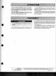
MVSTALLATION
WHEN INSTALLING THIS PRODUCT. . .
1. Read these tnstructions carefully. Failure to follow
them could damage the product or cause a hazardous
condition.
2. Check the ratings given in the instructions and on
the product to make sure the product is suitable for your
application.
3. Installer must be a trained, experienced service
technician.
4. After installation is complete, check out product
operation as provided in these instructions.
ND MOUNTING
.,
,I
The L4080 or L8080 is mounted in a tapping which is
usually provided by the boiler manufacturer, at a location
where it will sense average water temperatures.
1. Disconnect power supply and drain boiler.
2. If no tapping is provided, prepare one at a location
that will permit boiler water of average temperature to
circulate freely about the element.
3. L4080A-insert in boiler tapping. Using wrench on
hex nut only, tighten securely. Do not use the L4080 as a
lever to tighten the connection.
4. L4080B,D and L8080A-install immersion well in
boiler tapping, tighten securely. Insert sensing element in
well, tighten setscrew.
5. Refill boiler and check for water leaks. If well needs
tightening, use wrench on hex nut only.
SETTINGS (L4080 only)
Because heating systems differ, follow the burner
manufacturer’s recommendations when selecting the
proper Aquastat controller setting.
Turn the notched wheel until the desired high limit
setting coincides with the arrowhead indicator at the side
of the switch.
On the L408OF and G, the second high limit is not
adjustable.
WIRING
Disconnect power supply before connecting wiring to
prevent electrical shock or equipment damage.
All wiring must comply with applicable codes and
ordinances.
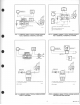
Wire the L4080 in the control circuit. Wire the L8080 in
series with the gas control power unit. Figs. 3-10 show
typical wiring diagrams.
4