
Install Instructions

L4008A,B,E,L; L6008A,G,H REMOTE BULB AQUASTAT
®
CONTROLLERS
The Aquastat® controller can be remotely mounted—
either vertically on a wall or panel, or directly on the boiler,
tank, or vessel.
If the system is filled, drain the system to a point below the
boiler tapping, or to wherever the sensing bulb is to be
installed.
Mounting the Case
Remove the cover and fasten the case to the wall or
panel using the three mounting holes in the back of
the case.
When mounting the remote bulb, if desirable, route
the tubing to run through any of the other three
corner notches in the case. Be careful not to kink or
bend tubing sharply. Be sure bends have at least 1 in.
(25.4 mm) radius.
Installing Remote Bulb with Immersion Well
Fit well, if used, to sensing bulb snugly for good thermal
response. Insert bulb until it rests against the bottom of the
well; then hold it there while tightening the tubing clamp.
Screw the well into the boiler, tank or pipe tapping.
Insert the bulb into the well, pushing the tubing until
the bulb bottoms in the well.
Attach the retainer clamp to the end of the well spud.
Loosen the draw nut and spread the jaws of the
clamp with the screwdriver if necessary.
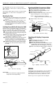
With the retainer clamp attached to the well spud (be
sure jaws of clamp hook over ridge at end of the
spud, as shown in Fig. 2, points A). Adjust tubing to fit
through retainer clamp groove, as shown at point B.
Tighten the draw nut so the retainer clamp is firmly
attached to the well spud and the tubing is held by
the clamp.
INSERT— MOUNTING CLAMP
SCREWDRIVER
SPREAD JAWS
TO FIT OVER
RIDGE ON
WELL SPUD
JAWS
DRAW
M8777
WELL
BULB
SPUD
MOUNTING
CLAMP
A
NUT
TUBING
B
Fig. 2. Immersion well fitting.
IMPORTANT
Do not secure draw nut so tightly that retainer
clamp could cut or collapse tubing.
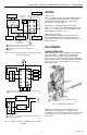
Mounting with Bulb Compression Fitting
Screw the fitting into the boiler or pipe tapping.
Slide sealing washer onto the bulb.
Insert the bulb into the fitting until bulb bottoms.
Slide split sleeve into fitting.
Place clamps A and B on assembly so that sleeve is
drawn into fitting when screws are tightened.
NOTE: Make sure that the nub on clamp A
engages space between sleeve and clamp.
Tighten clamp screws evenly.
M8815
CLAMP B
CLAMP A
CLAMP SCREWS (2)
BULB
COMPRESSION
FITTING
SEALING
WASHER
BULB
INSERTION LENGTH
APPROX. 3-3/16 IN. (81 MM)
SPLIT SLEEVE
Fig. 3. Bulb compression fitting.
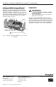
Mounting with Capillary Compression
Fitting
Screw fitting into the boiler or pipe tapping.
Place packing nut on tubing.
Slide bulb completely through fitting.
Place composition disc and 4 slotted brass washers
on tubing in the order shown in Fig. 4. Turn brass
washers so that slots are 180 degrees to each other.
Slide seal assembly into fitting and tighten packing nut.
COMPOSITION DISK
(SLOTTED)
BOILER PLUG
CAPILLARY TUBING
EXAMPLE OF SLOTTED WASHERS
ASSEMBLED
IN PAIRS:
PACKING NUT
M8816
IMMERSION
BULB
Fig. 4. Capillary compression fitting.
WIRING
All wiring must agree with applicable codes and ordinances
and regulations in such matters as wire size, type of
insulation, and enclosure. The controllers are provided
with conduit knockouts in the top and bottom of case.
Refer to Fig. 5 or 6 for a typical connection diagram.
95-5971—2
2