
Install Instructions

L4008A,B,E,L; L6008A,G,H REMOTE BULB AQUASTAT
®
CONTROLLERS
L1
(HOT)
L2
2
L4008A OR E
HIGH LIMIT
CONTROLLER
L6008A
CIRCULATOR
LOW LIMIT
R
W
B
CIRCULATOR
IGNITION
TRANSFORMER
RA89A RELAY
RA817A
PROTECTORELAY®
CONTROL
BURNER MOTOR
24V THERMOSTAT
2
1 3
4
T
T
1
2
3
4
CONTROLLER
1
POWER SUPPLY. PROVIDE DISCONNECT MEANS AND
OVERLOAD PROTECTION AS REQUIRED.
2
SELECT MODELS HAVE 1/4 IN. TAB TERMINAL FOR W
TERMINAL.
M8785
1
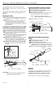
Fig. 5. Typical oil-fired hydronic heating system with
domestic hot water.
1
L1
L2
(HOT)
1
POWER SUPPLY. PROVIDE DISCONNECT MEANS AND OVERLOAD
PROTECTION AS REQUIRED.
L4008L
HL
TEMP
RA890F
6
5
T
4
T
3
F 1
2
2
G
NC NO
COM
PILOT
VALVE
IGNITION
MAIN
VALVE(S)
M4672
L1
(HOT)
L2
1
1
POWER SUPPLY. PROVIDE DISCONNECT MEANS AND OVERLOAD
PROTECTION AS REQUIRED.
JUMPER
HEATING LOAD
NO. 2
HEATING LOAD
NO. 1
R R
B B
W W
2 1
L6008G
SETTING
Control Point:
Insert a screwdriver in the slotted head visible through the
cover, and turn the indicating dial to the control point.
Temperature settings should be according to boiler
manufacturer’s recommendations.
Differential (on adjustable differential models):
Remove cover and move the differential adjustment wheel
(Fig. 1 or 7) to a point on the scale corresponding to the
desired differential. Replace cover.
Manual Reset (L4008E):
After boiler water temperature has dropped to a point
below the high limit setting, less differential, the reset
button at the front of the case must be pushed before the
burner can operate.
ADJUSTMENTS
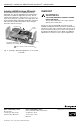
Adjusting Differential
Set the differential to correspond with the boiler manufacturer
recommendations. To adjust models with adjustable
differential, rotate the wheel on the back of the snap
switch, see Fig. 7, until the desired reading is aligned with
the V notch in the frame. The wheel provides as adjustment
from 5° to 30°F (3° to 17°C). Replace the cover on the
Aquastat® controller.
DIFFERENTIAL
WHEEL
NOTCH IN
FRAME
SNAP
SWITCH
SELECT MODELS HAVE A SCREW TERMINAL INSTEAD
1
1
OF TAB TERMINAL.
M8969
Fig. 7. Adjusting the differential.
Adjust the control point to correspond with the boiler
manufacturer recommendations. To adjust, insert a
screwdriver in the slotted screw type head located beneath
the window in the cover. Turn the scale to the desired
control point.
M8968
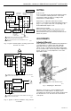
Fig. 6. Typical oil burner installation using L4008L
or L6008G.
3
95-5971—2