
Install Instructions

L4008A,B,E,L; L6008A,G,H
Aquastat
®
Controllers
APPLICATION
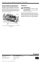
These remote bulb (see Fig. 7), immersion type (see Fig. 1)
controllers operate in response to temperature changes in
hydronic heating systems and other heated liquids.
Electrical Ratings:
Switch ratings are shown on the inside cover of each
device. The electrical requirements on controlled equipment
must not exceed this rating.
L4008A—breaks the burner circuit on a rise in water
temperature. It is normally used as a limit controller.
When used as an operating controller or low limit, a
separate high limit control must be used.
L4008B—makes a control circuit on a rise in water
temperature. It is normally used as a circulator
controller to prevent circulator operation until boiler
water temperature is at or above the control setting.
L4008E—breaks the burner circuit and locks out on a
rise in water temperature. It is used as a high limit
controller where manual reset is desirable.
L4008L—is used as a 2-stage Aquastat® controller.
L6008A—makes the burner circuit on a drop in water
temperature. It is normally used as a circulator and
low limit cooling controller.
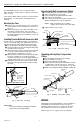
M8806
SETPOINT
INDICATING DIAL
DIFFERENTIAL
ADJUSTMENT
WHEEL
ADAPTER CLAMP
SCREWS
INSERTION
ELEMENT
WITH VERTICAL MOUNTING OF IMMERSION WELL,
ELEMENT IS ATTACHED TO BOTTOM OF THE CASE.
SELECT MODELS HAVE SCREW TERMINAL, NOT TAB
TERMINAL.
2
1
1
2
Fig. 1. Internal view.
®U.S. Registered Trademark
Copyright © 1995 Honeywell Inc. • All Rights Reserved
INSTALLATION INSTRUCTIONS
L6008G—is used as a 2-stage Aquastat® controller to
cycle 2-stage gas valve.
L6008H—is used as a low fire Aquastat® controller.
If immersion well or capillary compression fitting must be
ordered, refer to form 68-0040, Wells and Fittings for
Temperature Controllers, for part numbers and ordering
information.
INSTALLATION
When Installing this Product…
1. Read these instructions carefully. Failure to follow
them could damage the product or cause a hazard-
ous condition.
2. Check the ratings given in the instructions and on
the product to make sure the product is suitable for
your application.
3. Installer must be a trained, experienced service
technician.
4. After installation is complete, check out product
operation as provided in these instructions.
CAUTION
Disconnect power supply before installation to
prevent electrical shock or equipment damage.
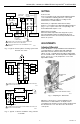
Depending on model and installation requirements, install
the temperature sensing bulb either in an immersion well
(see Fig. 2) that extends into the boiler or tank, or directly
immerse the temperature sensing bulb in the liquid. For
installations not using a well, secure the bulb with a bulb
compression fitting (see Fig. 3), or a capillary compression
fitting (see Fig. 4). Order the well or the fitting separately.
The boiler manufacturer generally provides a tapping for
inserting the Aquastat® controller sensing element. Locate
this tapping in a representative point where typical water
temperature can be measured. Never locate the bulb or
protecting immersion well close to a hot or cold water inlet
or steam coil. Install the bulb in the supply line of an
indirect water heater, in the indirect water heater itself, or
in the feed riser about 6 in. (152 mm) above the boiler. If
the riser is valved, install the bulb between the boiler and
the valve.
95-5971-2