
User Guide
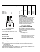
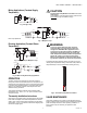
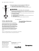
Table Of Contents

AM-1 SERIES “R MODEL” - HEATING ONLY
62-3106—01 2
ORDERING INFORMATION
When purchasing replacement and modernization products from your TRADELINE® wholesaler or distributor, refer to the
TRADELINE® Catalog or price sheets for complete ordering number.
If you have additional questions, need further information, or would like to comment on our products or services, please write or
phone:
1. Your local Honeywell Automation and Control Products Sales Office (check white pages of your phone directory).
2. Honeywell Customer Care
1885 Douglas Drive North
Minneapolis, Minnesota 55422-4386
In Canada—Honeywell Limited/Honeywell Limitée, 35 Dynamic Drive, Toronto, Ontario M1V 4Z9.
International Sales and Service Offices in all principal cities of the world. Manufacturing in Australia, Canada, Finland, France,
Germany, Japan, Mexico, Netherlands, Spain, Taiwan, United Kingdom, U.S.A.
Table 1. AM-1 Union Connections
.
Fig. 1. Dimension Diagram.
VALVE ADJUSTMENT
To adjust temperature setting of the mixing valve. Loosen
hand wheel screw, lift handwheel and turn to desired
temperature, push the hand wheel on the retighten screw.
APPLICATION
The AM-1 SERIES “R Model” - Heating Only is a valve for
heating applications ONLY.
INSTALLATION
NOTE TO INSTALLER:
This product should be installed by a qualified individual, in
accordance with local codes and ordinances. It is the
responsibility of the installer to properly select, install and
adjust these devices as specified in these instructions. For
installations, which require compliance with Building/
Mechanical/Plumbing Codes, the appropriate AM-1 Series
Valve must be chosen and installed and the discharge
temperature set and locked according to these instructions.
These valves should be installed where they will be
accessible for cleaning, servicing or adjustment.
NOTE: Pressure difference between Hot and Cold ports
should not exceed 10 psi (69 kPa).
TYPICAL INSTALLATION DIAGRAMS
Space Heating
Boiler must operate at a water temperature higher than the
desired temperature in the heating system in order to perform
at maximum efficiency.
Example: Radiant floor heating.
SYMBOLS
1 = Check Valve/Flow Check
2 = Alternate Pump Location
T= Pump Control Thermostats
NOTES:
• Install recirculation pump between last fixture and
water heater.
• Use a pump control thermostat where shown.
Recirculation pump should not run continuously.
Product Number
Size
in. Connection Type
Max Flow
GPM
Cv
in.
A
in. (mm)
B
in. (mm)
C
in. (mm)
AM100R-US-1 1/2
Union Sweat
8
3.9 3.15 (80)
2.7 (69) 4.4 (112)
AM101R-US-1 3/4 12 2.9 (73) 4.9 (124)
AM102R-US-1 1 16 3.5 (89) 6.1 (155)
AM100R-UT-1 1/2
Union Threaded
8 2.9 (73) 4.8 (122)
AM101R-UT-1 3/4 12 3.8 (97) 6.5 (165)
AM102R-UT-1 1 16 3.9 (99) 7.0 (178)
AM100R-UPEX-1 1/2
Union PEX
8 3.1 (79) 5.3 (135)
AM101R-UPEX-1 3/4 12 3.1 (79) 5.3 (135)
M23938
MIX
H
C
B
C
2-1/4
(57)
A
Ø 1-51/64
(46)