
User Guide
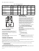


Table Of Contents

Automation and Control Solutions
Honeywell International Inc. Honeywell Limited-Honeywell Limitée
1985 Douglas Drive North 35 Dynamic Drive
Golden Valley, MN 55422 Toronto, Ontario M1V 4Z9
customer.honeywell.com
AM-1 SERIES “R MODEL” - HEATING ONLY
® U.S. Registered Trademark
© 2008 Honeywell International Inc.
62-3106—01 J.I. Rev. 01-08
Fig. 7. Exploded View
TYPICAL SPECIFICATION
Temperature Setting Range (as required, see page one),
Maximum Pressure rating of 150 psi (1034 kPa), Maximum
Hot inlet temperature of 212° F (100° C), Nickel plated Brass/
Bronze construction, Teflon coated valve body wear surface,
Teflon coated brass shuttle, EPDM O-rings, proportional
design (simultaneous control of hot and cold ports), with either
sweat union, NPT (female) union or union PEX connections.
Valve for domestic hot water applications shall have
temperature lock. Design shall be straight thru, with hot and
cold ports at the same level. The design shall permit easy
access for maintenance, with replaceable thermostatic
element.
Thermostatic Element Replacement
Kit - AM-1-025 RP
Teflon
®
is a registered trademark of E.I. Du Pont De Nemours and Company.
Tradeline
®
is a registered trademark of Honeywell International. Inc.
M23941
LOWER ASSEMBLY
HANDWHEEL
DIFFUSER
SPRING
VALVE BODY
TOP ASSEMBLY
LOWER NUT
UPPER NUT
O RING
RETAINING RING
C
H
MIX
H
To Clean and/or Replace the Lower Assembly Shut Off Water and:
1. With a screwdriver remove screw and hand wheel.
2. Unscrew lower nut (counterclockwise). This removes top assembly.
3. Brass top assembly will pop up. Remove lower assembly, diffuser and spring.
WARNING
Do not use solvents or scratch metallic / Teflon coated surfaces.
4. Carefully remove any scaling (calcium deposits) or foreign particles from valve seat and
other internal parts. Use vinegar to remove calcium. Soak parts until calcium becomes soft
and can be scrubbed and washed off.
5. Replace cleaned spring, diffuser and lower assembly following instructions below or use
new replacement kit assembly.
A. Insert spring onto diffuser.
B. Insert diffuser with spring end first into body.
C. Fit valve top assembly into lower assembly and insert into valve. Tighten lower nut.
D. Tightening upper nut.
E. Place handwheel on valve.
F. Turn handwheel to desired temperature setting and insert screw.